Fun simulation of a Chain in Android

DSC00071In this post I simulate a Chain in Android using AndEngine & Box2D physics. Simulating a Chain is fairly straightforward. Initially I create a static point as an anchor point to suspend the Chain from

You can see the video at Fun simulation of a Chain in Android – I on Youtube

The project can be cloned from GitHib at Chain


link[0] = new Sprite((float) 360, (float) 20, this.mLinkTextureRegion, this.getVertexBufferObjectManager());

linkBody[0] = PhysicsFactory.createBoxBody(this.mPhysicsWorld, link[0], BodyType.DynamicBody, FIXTURE_DEF);

this.mPhysicsWorld.registerPhysicsConnector(new PhysicsConnector(link[0], linkBody[0], true, true));

this.mScene.attachChild(link[0]);

Then I create succeeding links to the initial link with revolute joints between them as follows

// Add links to chain with revolute joint between each link

for(int i =1; i < nBodies ; i++){

x[i] = x[i-1] + 8 * Math.cos(PI/4);

y[i] = y[i-1] + 8 * Math.sin(PI/4);

link[i] = new Sprite((float) x[i], (float) y[i], this.mLinkTextureRegion, this.getVertexBufferObjectManager());

linkBody[i] = PhysicsFactory.createBoxBody(this.mPhysicsWorld, link[i], BodyType.DynamicBody, FIXTURE_DEF);

this.mPhysicsWorld.registerPhysicsConnector(new PhysicsConnector(link[i], linkBody[i], true, true));

this.mScene.attachChild(link[i]);

revoluteJointDef = new RevoluteJointDef();

revoluteJointDef.initialize(linkBody[i], linkBody[i-1], linkBody[i-1].getWorldCenter());

revoluteJointDef.enableMotor = false;

revoluteJointDef.motorSpeed = 0;

revoluteJointDef.maxMotorTorque = 0;

this.mPhysicsWorld.createJoint(revoluteJointDef);

Finally I suspend a monkey as the last body to the Chain.

I have added plated for the 2 walls (right & left) and also the floor as collisions can be detected between bodies.

@Override

protectedvoid onManagedUpdate(finalfloat pSecondsElapsed) {

// Check collisions

if(rWall.collidesWith(this) ){

x = this.getX();

y = this.getY();

bText.setPosition(x-40,y – 20);

bText.setText(“Bonk!”);

}

if(lWall.collidesWith(this)){

x = this.getX();

y = this.getY();

bText.setPosition(x + 20,y – 20);

bText.setText(“Thump!”);

}

if(floor.collidesWith(this)){

x = this.getX();

y = this.getY();

bText.setPosition(x – 20,y – 20);

bText.setText(“Thud!”);

}

With all these under gravity we have a nice Chain effect!

You see the video at Fun simulation of a Chain in Android – I

The project can be cloned from GitHib at Chain

Take a look at some cool simulations using AndEngine & Box2D
1. The making of Total Control Android game
2. Simulating an Edge Shape in Android
3. Simulating a Web Joint in Android
4. Modeling a Car in Android
5. A closer look at “Robot horse on a Trot! in Android”
and a couple more
Find me on Google+

Modeling a Car in Android

DSC00065

In this post I give the details of how I modeled a ‘running car’ in Android using AndEngine & Box2D physics.  This post is based on a great blog post by Emanuele Feronato on “Step by step creation of a Box2D car/truck with motors and shocks”.

You can check the video of this simulation at “Modeling a Car using AndEngine & Box2D physics
You can clone the entire project from GitHub at Wheels

So getting down to the “nuts & bolts” of  creating a car we need to create 3 components of the car

1)Car body

2)Axles (left & right)

3)Wheels (left & right)

The car body is connected to the axles through a prismatic joint. Prismatic joint, also known as ‘slider joint’, allows 2 bodies to move relative to each on a single axis of motion. Hence this joint simulates a ‘shock absorber’ effect very nicely. In fact, in the 3rd lap of my video from right to left when the car collides with the left wall you can see the car rocking on its axles. This is done as below

/* Connect the front axle to car using a prismaticJoint */

PrismaticJointDef front = new PrismaticJointDef();

front.initialize(carBody, frontAxle, frontAxle.getWorldCenter(),new Vector2(0f,1f));

front.collideConnected=false;

front.enableMotor=false;

front.enableLimit=true;

front.upperTranslation=0.5f;

front.lowerTranslation=-0.2f;

PrismaticJoint mFront = (PrismaticJoint) mPhysicsWorld.createJoint(front);

The wheels are connected to the axles through a revolute joint. A revolute joint rotates around an anchor point based on a specified motor speed and motor torque as shown below

//Connect rear wheel to rear axle using revoluteJoint
final RevoluteJointDef revoluteJointDef2 =new RevoluteJointDef();
revoluteJointDef2.initialize(wheelBody2, rearAxle, wheelBody2.getWorldCenter());
revoluteJointDef2.enableMotor =true;
revoluteJointDef2.motorSpeed =-50;
revoluteJointDef1.maxMotorTorque = 10;
rj2 =(RevoluteJoint)this.mPhysicsWorld.createJoint(revoluteJointDef2);

I wanted the car to reverse direction when it collided with either the left wall or right wall. In my original code, the car body and the walls were made of rectangle shapes and I was not able to detect the collisions. So I changed the car body and add a left wall and a right wall with sprites and checked for the collisions between these bodies. Fortunately I had done this collision detection in my app “The making of the Dino Pong Android Game”. I was able to check for collisions as shown below .

@Override
protectedvoidonManagedUpdate(finalfloat pSecondsElapsed){
// Check collisions
if(rWall.collidesWith(this)|| lWall.collidesWith(this)){

// On collision reverse speed
rj1.setMotorSpeed(-(rj1.getMotorSpeed()));
rj2.setMotorSpeed(-(rj2.getMotorSpeed()));
}

If you have done all of the above and also managed to utter the magic incantation (which I will not divulge ;-)) you should have a cute running car!  

You can check the video of this simulation at “Modeling a Car using AndEngine & Box2D physics

You can clone the entire project from GitHub at Wheels


Take a look at some cool simulations using AndEngine & Box2D
1. Simulating the domino effect using Box2D and AndEngine
2. Bull in a china shop – Behind the scenes in android
3. Simulating an Edge Shape in Android
4. Fun simulation of a Chain in Android
5. “Is it animal? Is it an insect?” in Android
and many more …

Find me on Google+

Simulating a Web Joint in Android

a (1) I got interested in this demo after I saw the Java demo of Box2D physics in Jbox (look in Joints). Moreover my interest in this demo was heightened as the Disney game ‘Cut the rope’ possibly uses some elements of a web joint.

Take a look at the simulation Simulating a Web Joint in Android on Youtube
You can clone the entire project from GitHub at WebJoint

The first task was to create & place Animated Sprites(face) at the corners of a rectangle. I also added distance Joints between them.

Vector2 v1 = new Vector2(p1[0]/PIXEL_TO_METER_RATIO_DEFAULT,p1[1]/PIXEL_TO_METER_RATIO_DEFAULT);

Vector2 v2 = new Vector2(p2[0]/PIXEL_TO_METER_RATIO_DEFAULT,p2[1]/PIXEL_TO_METER_RATIO_DEFAULT);

distanceJoint.initialize(body1, body2, v1, v2);

distanceJoint.collideConnected = true;

distanceJoint.dampingRatio = 1.0f;

distanceJoint.frequencyHz = 10.0f;

this.mPhysicsWorld.createJoint(distanceJoint);

}

I also had to draw connecting lines to represent the joints between the faces The challenge is to update these lines in real time as the bodies oscillate about their mean based on the damping constant. Fortunately I had done this in of my earlier demos “Creating a blob with an attitude”. The key to this is to update the connecting line to the attached bodies through the onUpdate method

@Override

publicvoid onUpdate(finalfloat pSecondsElapsed) {

super.onUpdate(pSecondsElapsed);

if(connectionLine != null)

connectionLine.setPosition(faceA.getX(),faceA.getY(),faceB.getX(),faceB.getY());

}

}

While the Animated Sprites are dynamic bodies I also created 4 pegs (static bodies) that attach to these 4 animated sprites which are suspended in a rectangle formation.

I also added a onAreaTouch listener to enable me to remove bodies interactively. This is a deviation from the demo where the user has to press a key which will remove the bodies in a pre-determined fashin.

To remove the bodies using onAreaTouch was a challenge. So when I remove an Animated Sprite I have to

  1. Remove all connecting lines to the body

  2. Destroy all the joints between the body and other bodies

TO remove the connecting lines I first tried the following

private void removeFace(AnimatedSprite face) {

if(connectionLine1 != null && connectionLine1.collidesWith(face)){

this.mScene.detachChild(connectionLine1);

connectionLine1.dispose();

connectionLine1 = null;

}

if(connectionLine2 != null && connectionLine2.collidesWith(face)){

..

But this did not quite work and it would remove only some of the lines. Then I changed it as follows based on the animated sprite that is being removed in which I specifically remove the connecting lines

if(face.equals(face1)){

Log.d(“Yes”,“Yes”);

destroyLine(connectionLine1);

destroyLine(connectionLine4);

destroyLine(connectionLine5);

}

where destroyLine() is as follow

if(line.isDisposed() == true)

return;

this.mScene.detachChild(line);

final PhysicsConnector linePhysicsConnector= this.mPhysicsWorld.getPhysicsConnectorManager().findPhysicsConnectorByShape(line);

this.mPhysicsWorld.unregisterPhysicsConnector(linePhysicsConnector);

line.dispose();

line = null;

}

To destroy all the distance joints which the bodies has we have to iterate through all of the joints as follows

// Determine all joints connected to Animated Sprite & destroy

ArrayList<JointEdge> jointsEdge = facePhysicsConnector.getBody().getJointList();

for(int i=0; i < jointsEdge.size(); i++){

Joint j = jointsEdge.get(i).joint;

this.mPhysicsWorld.destroyJoint(j);

j=null;

}

Finally the face is removed as follows

this.mPhysicsWorld.unregisterPhysicsConnector(facePhysicsConnector);

this.mPhysicsWorld.destroyBody(facePhysicsConnector.getBody());

this.mScene.unregisterTouchArea(face);

this.mScene.detachChild(face);

Anyway occasionally I do get a SIGSEGV in update thread if I remove face as follows lower right, lower left, upper left. Some orders work well for e.g. Upper left, lower left, lower right etc.

If you figure out what I am missing do let me know.

Take a look at the simulation Simulating a Web Joint in Android

You can clone the entire project from GitHub at WebJoint

Find me on Google+

Simulating an Edge Shape in Android

Here is a small post on how I managed to simulate an Edge Shape in Android. I wanted to do this after I saw the Java demo of Box2D in JBox2D(see RayCast). For the Edge Shape I chose a cosine curve. I used the same method I used, mentioned in my earlier post “Making of the Total Control Android Game

The simulation can be seen at Simulating an Edge Shape on YouTube
You can clone the entire project from Github at EdgeShape.

Since it is a cosine curve I place a ball shape for every point on a cosine function, close to each other to seem continuous and create a body from the Sprite with physical properties.

for (int i = 0; i < nBodies; ++i)

{

float angle = (float) ((10.0 * PI * i)/180.0);

float y1 = 300 + (float)Math.cos(angle/20) * 120;

//Log.d(“Test”,”Test” + “x:” + x1 +”y:”+ y1);

circles[i] = new Sprite(x1, y1, this.mBallTextureRegion, this.getVertexBufferObjectManager());

circlesBody[i] = PhysicsFactory.createCircleBody(this.mPhysicsWorld, circles[i], BodyType.StaticBody, FIXTURE_DEF);

this.mScene.attachChild(circles[i]);

x1 = (float) (x1 + 0.5);

}

So this can be done for every mathematical curve. I also intended to create other curves like the Archimedes Spiral and the Lemniscate. Maybe I will leave that for a rainy day!! 🙂

However, I am not sure how to create a irregular edge shape. I will probably figure that out.

The egde shape is made to be a STATIC_BODY. I then took code of creating Animated Sprites at the point where I touch from AndEngine examples (PhysicsExample.java). To make the simulation more fun I also added a Linear Impulse to the Animated Sprite.

face = new AnimatedSprite(pX, pY, this.mCircleFaceTextureRegion, this.getVertexBufferObjectManager());

body = PhysicsFactory.createCircleBody(this.mPhysicsWorld, face, BodyType.DynamicBody, gameFixtureDef);

face.animate(200);

body.applyLinearImpulse(-200,200,pX,pY);

The effect is better if the phone is horizontal to the ground and not so great if the phone is kept vertical and the bodies do not seem to shoot off.

The simulation can be seen at Simulating an Edge Shape

You can clone the entire project from Github at EdgeShape.


Take a look at some cool simulations using AndEngine & Box2D
1. Simulating the domino effect using Box2D and AndEngine
2. Blob with an attitude(stiffness) in Android
3. The making of Total Control Android game
4. Simulating a Web Joint in Android
20. A closer look at “Robot horse on a Trot! in Android”
and many more …
Find me on Google+

Maximizing enterprise bandwidth by sharing global enterprise-wide network resources

Here is a slightly wild idea of mine

Introduction

Generally in enterprises the network bandwidth available to employees is greatest at the start of the working day and progressively becomes bad as the day progresses. The bandwidth available improves again later in the day. The reason is that the bandwidth demand is highest during the middle portions of the day usually between 10 am – 5pm when the number of employees are the highest. The poor response times during the day are common to many enterprises as the network infrastructure is stretched beyond its designed capacity

Description

This post looks at a novel technique where the increasing bandwidth is ‘outsourced’ to other geographical regions. In other words the increasing bandwidth requirement is ‘borrowed’ from the network infrastructure from other regions.

This idea visualizes the user of a network devoice (Time Zone –Traffic Director Switch) that borrows bandwidth based on the time-of-day and the bandwidth shortage in a particular region. This device effectively borrows the idle network resources (routers, hubs, switches) from other geographical regions thus resolving the bandwidth issue.

In large global organizations, office are spread throughout the world. There will be typical daytimes and night times.  Night time usages will be minimal unless the office works on shifts

Large enterprises typically use leased lines between their various offices spread across the globe. Each of the regional offices will have its own set of routers, Ethernet switches, hubs etc.

 1

The leased lines and the network infrastructure will experience peak usage during the daytime which will subside during the region’s night times. This idea looks at a scheme in which the leased line and the network infrastructure at region B are utilized during the regions’ night times to supplement the bandwidth crunch in region A’s day time

In a typical situation we can view that the enterprise’s region as the center of the network resources (hubs, routers, switches) in its own region. Simplistically we can represent this as shown in Fig 1

 2

This post visualizes the realization of a network device namely the Time Zone-Traffic Director Switch which effectively borrows bandwidth based on the time-of-day and the bandwidth shortage in a particular region.,

This device effectively borrows the idle network resources (routes, hubs switches) from other geographical regions this resolving the bandwidth issue. Such a network device can be implemented using the Open Flow Protocol which can virtualize the network resources

In large cloud computing systems like Facebook, Google, Amazon, which have data centers spread throughout the world, traffic is directed to a data center closest to the user to minimize latency, In this scheme the use of the network resources in other geographical regions may introduce network latencies but will be economically efficient for the enterprises.

In fact this Time Zone-Traffic Director can be realized through the use of the Open Flow Protocol and Software Defined Networks (SDNs)

Detailed Description

This post utilizes a scheme in which the network resources from another are used to supplement the network resources at region during its daytimes. The leased lines and the network resources in other regions during their nights will typically experience low utilization of both the leased line capacity and the network infrastructure capacity. So in this method the bandwidth resources are borrowed from another region where the utilization of the network resources is low. This supplements the bandwidth in the region which is experiencing a bandwidth shortage. This scheme can be realized by the utilization of the Software Defined Network using the Open Flow protocol.

The Open Flow protocol has a Flow Controller which can virtualizes the network resources. This method visualizes virtualizing the network resources of a corporate office that is spread geographically around the world to optimize the corporate’s resources

This is how the scheme will have to be realized

  1. Over dimension the leased line capacity to be at least 30%-40% more than the total capacity of it Ethernet switches gigabit routers etc.  So if the network resource at a region is 16Gbps then the leased line capacity should be of the order of 20Gpbs
  2. When an external site is to be accessed for high speed connection,  after the DNS resolution the packets must be sent to the Time Zone –  Traffic Director Switch
  3. The Time Zone – Traffic Director Switch will determine the bandwidth availability at that time.  Let us assume that the regional network resources are experiencing peak usage It will not decide to use the network resources of another region
  4. The Time Zone – Traffic Director Switch will now check the time of the day.  If it is the ‘regional day’ (e.g. 10 am – 5pm, when the usages is highest) it will hard code the next hop to be a router in another geographical region. SO if the traffic is to originate in Bangalore, the next hop, if there is bandwidth crunch will be in another a router in Europe, or in the US.
  5. The Time Zone – Traffic Director Switch can be realized through th e use of the Open Flow protocol
  6. By artificially redirecting the traffic to another region all packets will be re-routed to use the leased lines & network resources from the other region thus giving the region, Bangalore, in this case, more bandwidth

This can be represented in the following diagram

 3

In the figure below The Time Zone – Traffic Director Switch uses the regions ‘internal’ network resources since it does not face a bandwidth crunch

 3

In the next figure the Time Zone – Traffic Director Switch borrows the network resource from Region B

5

This scheme will introduce additional latency as opposed to the Shorted Path First (SPF) or the Distance Vector Algorithm (DVA) However the enterprise gets to use its network infrastructure more effectively. This will result in the enterprise’s network infrastructure to be used more efficiently and effectively reducing the CAPEX and OPEX for the entire organization.

The entire scheme can be represented by the flow chart below

 6

Conclusion

The tradeoff in this scheme is between the economics of reusing the network and the leased line infrastructure of the enterprise versus the additional latency introduced

However the delay will be more than compensated by the increase in the bandwidth available to the end user. This idea will simultaneously solve the problem of the bandwidth crunch while efficiently and effectively utilizing the network resources across the entire enterprise. This scheme will also reduce the organization CAPEX and OPEX as resources are used more efficiently.

Thoughts?

Find me on Google+

The making of Total Control Android game

tc-1This game of Total Control was one of those games I played when I was a kid when there were no Smartphone or iPods. It was a simple, circular toy with small balls which you had to slowly nudge to the innermost circle. I have been wanting to replicate this game on Android for some time.

The game can be  downloaded from Google Play at Total Control
The Total Control project can be cloned from Git Hub at Total Control

I had decided to use AndEngine & Box2D physics for this. I was under the assumption that creating those concentric circles would be a breeze with AndEngine and Box2D physics. However it took me some time to figure out how to create these circles. Eventually I realized that each circle could be created by computing the circumference of the concentric circle and placing tiny circle bodies. Each of these tiny circles are of type BodyType.StaticBody. So they have physical properties of a ring on which other bodies can roll. With this solved the rest of the implementation was quite straight forward.
– Small colored balls were placed in different spots in the concentric circles.
– Small gaps were created like the real game to move to an inner circle

Finally the whole game uses the Accelaration Sensor and uses Gravity for movement of the balls much like the real game.

tc-2

I also wanted to include AdMob into the game. Here is a good link at WikiHow with all the steps for adding AdMob to your app.

However the above link provides a method of placing the Ad in your desired layout’s XML file. Since my game was based on AndEngine the method to place an Ad in the game uses the FrameLayout. The complete code is given here the AndEngine Forum. To test the working of the Ads make sure you add the code

// REQUEST an ad (Test ad) //
AdRequest adRequest = new AdRequest();
adRequest.addTestDevice(“<Your device Id from the Console”); //Comment this line when publishing
adView.loadAd(adRequest);

You should get your device id when your run your application in Eclipse in the Console tab. When you run the app you should see the Ad. You may have to adjust your app to allow for teh Ad. I had to move and shrink my Game to allow for the Ad display at the bottom.

You can download the game from Google Play at Total Control
The Total Control project can be cloned from Git Hub at Total Control

Find me on Google+

Architecting a cloud based IP Multimedia System (IMS)

Here is an idea of mine that has been slow cooking in my head for more than 1 and a 1/2 year. Finally managed to work its way to IP.com. See link below

Architecting a cloud based IP Multimedia System (IMS) 

The full article is included below

Abstract

This article describes an innovative technique of “cloudifying” the network elements of the IP Multimedia (IMS) framework in order to take advantage of keys benefits of the cloud like elasticity and the utility style pricing. This approach will provide numerous advantages to the Service Provider like better Return-on-Investment(ROI), reduction in capital expenditure and quicker deployment times,  besides offering the end customer benefits like the availability of high speed and imaginative IP multimedia services

Introduction

IP Multimedia Systems (IMS) is the architectural framework proposed by 3GPP body to establish and maintain multimedia sessions using an all IP network. IMS is a grand vision that is access network agnostic, uses an all IP backbone to begin, manage and release multimedia sessions. This is done through network elements called Call Session Control Function (CSCFs), Home Subscriber Systems (HSS) and Application Servers (AS). The CSCFs use SDP over SIP protocol to communicate with other CSCFs and the Application Servers (AS’es). The CSCFs also use DIAMETER to talk to the Home Subscriber System (HSS’es).

Session Initiation Protocol (SIP) is used for signaling between the CSCFs to begin, control and release multi-media sessions and Session Description Protocol (SDP) is used to describe the type of media (voice, video or data). DIAMETER is used by the CSCFs to access the HSS. All these protocols work over IP. The use of an all IP core network for both signaling and transmitting bearer media makes the IMS a very prospective candidate for the cloud system.

This article  proposes a novel technique of “cloudifying” the network elements of the IMS framework (CSCFs) in order to take advantage of the cloud technology for an all IP network. Essentially this idea proposes deploying the CSCFs (P-CSCF, I-CSCF, S-CSCF, BGCF) over a public cloud. The HSS and AS’es can be deployed over a private cloud for security reasons. The above network elements either use SIP/SDP over IP or DIAMETER over IP. Hence these network elements can be deployed as instances on the servers in the cloud with NIC cards. Note: This does not include the Media Gateway Control Function (MGCF) and the Media Gate Way (MGW) as they require SS7 interfaces. Since IP is used between the servers in the cloud the network elements can setup, maintain and release SIP calls over the servers of the cloud. Hence the IMS framework can be effectively “cloudified” by adopting a hybrid solution of public cloud for the CSCF entities and the private cloud for the HSS’es and AS’es.

This idea enables the deployment of IMS and the ability for the Operator, Equipment Manufacturer and the customer to quickly reap the benefits of the IMS vision while minimizing the risk of such a deployment.

Summary

IP Multimedia Systems (IMS) has been in the wings for some time. There have been several deployments by the major equipment manufacturers, but IMS is simply not happening. The vision of IMS is truly grandiose. IMS envisages an all-IP core with several servers known as Call Session Control Function (CSCF) participating to setup, maintain and release of multi-media call sessions. The multi-media sessions can be any combination of voice, data and video.

In the 3GPP Release 5 Architecture IMS draws an architecture of Proxy CSCF (P-CSCF), Serving CSCF(S-CSCF), Interrogating CSCF(I-CSCF), and Breakout CSCF(BGCF), Media Gateway Control Function (MGCF), Home Subscriber Server(HSS) and Application Servers (AS) acting in concert in setting up, maintaining and release media sessions. The main protocols used in IMS are SIP/SDP for managing media sessions which could be voice, data or video and DIAMETER to the HSS.

IMS is also access agnostic and is capable of handling landline or wireless calls over multiple devices from the mobile, laptop, PDA, smartphones or tablet PCs. The application possibilities of IMS are endless from video calling, live multi-player games to video chatting and mobile handoffs of calls from mobile phones to laptop. Despite the numerous possibilities IMS has not made prime time.

The technology has not turned into a money spinner for Operators. One of the reasons may be that Operators are averse to investing enormous amounts into new technology and turning their network upside down.

The IMS framework uses CSCFs which work in concert to setup, manage and release multi media sessions. This is done by using SDP over SIP for signaling and media description. Another very prevalent protocol used in IMS is DIAMETER.  DIAMETER is the protocol that is used for authorizing, authenticating and accounting of subscribers which are maintained in the Home Subscriber System (HSS). All the above protocols namely SDP/SIP and DIAMETER protocols work over IP which makes the entire IMS framework an excellent candidate for deploying on the cloud.

Benefits

There are 6 key benefits that will accrue directly from the above cloud deployment for the IMS. Such a cloud deployment will

i.    Obviate the need for upfront costs for the Operator

ii.    The elasticity and utility style pricing of the cloud will have multiple benefits for the Service Provider and customer

iii.   Provider quicker ROI for the Service Provider by utilizing a innovative business model of revenue-sharing for the Operator and the equipment manufacturer

iv.   Make headway in IP Multimedia Systems

v.   Enable users of the IMS to avail of high speed and imaginative new services combining voice, data, video and mobility.

vi.   The Service Provider can start with a small deployment and grow as the subscriber base and traffic grows in his network

Also, a cloud deployment of the IMS solution has multiple advantages to all the parties involved namely

a)   The Equipment manufacturer

b)   The Service Provider

c)   The customer

A cloud deployment of IMS will serve to break the inertia that Operators have for deploying new architectures in the network.

a)   The Equipment manufactures for e.g. the telecommunication organizations that create the software for the CSCFs can license the applications to the Operators based on innovative business model of revenue sharing with the Operator based on usage

b)   The Service Provider or the Operator does away with the Capital Expenditure (CAPEX) involved in buying CSCFs along with the hardware.  The cost savings can be passed on to the consumers whose video, data or voice calls will be cheaper. Besides, the absence of CAPEX will provide better margins to the operator. A cloud based IMS will also greatly reduce the complexity of dimensioning a core network. Inaccurate dimensioning can result in either over-provisioning or under-provisioning of the network.  Utilizing a cloud for deploying the CSCFs, HSS and AS can obviate the need upfront infrastructure expenses for the Operator. As mentioned above the Service Provider can pay the equipment manufactured based on the number of calls or traffic through the system

c)   Lastly the customer stands to gain as the IMS vision truly allows for high speed multimedia sessions with complex interactions like multi-party video conferencing, handoffs from mobile to laptop or vice versa. Besides IMS also allows for whiteboarding and multi-player gaming sessions.

Also the elasticity of the cloud can be taken advantage of by the Operator who can start small and automatically scale as the user base grows.

Description

This article describes a method in which the Call Session Control Function (CSCFs) namely the P-CSCF, S-CSCF,I-CSCF and BGCF can be deployed on a public cloud.  This is possible because there are no security risks associated with deploying the CSCFs on the public cloud. Moreover the elasticity and the pay per use of the public cloud are excellent attributes for such a cloudifying process. Similarly the HSS’es and AS’es can be deployed on a private cloud.  This is required because the HSS and the AS do have security considerations as they hold important subscriber data like the IMS Public User Identity (IMPU) and the IMS Private User Identity (IMPI).  However, the Media Gateway Control Function (MGCF) and Media Gateway (MGW) are not included this architecture as these 2 elements require SS7 interfaces

Using the cloud for deployment can bring in the benefits of zero upfront costs, utility style charging based on usage and the ability to grow or shrink elastically as the call traffic expands or shrinks.

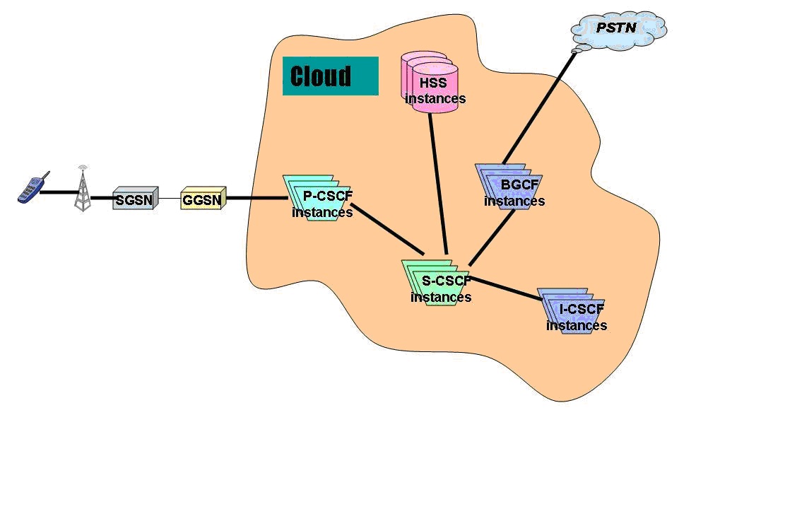
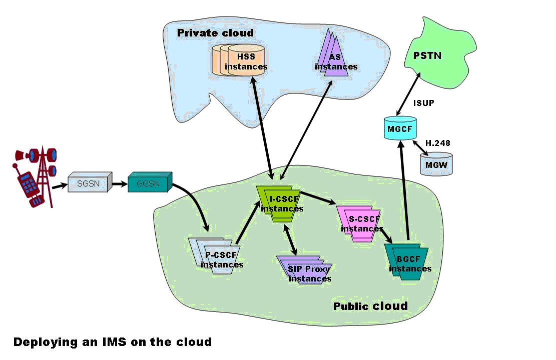
This is shown diagrammatically below where all the IMS network elements are deployed on a cloud.

In Fig 1., all the network elements are shown as being part of a cloud.

1

Fig 1. Cloudifying the IMS architecture.

Detailed description

This idea requires that the IMS solution be “cloudified “i.e. the P-CSCF, I-CSCF, S-CSCF and the BGCF should be deployed on a public cloud. These CSCFs are used to setup, manage and release calls and the information that is used for the call does not pose any security risk. These network elements use SIP for signaling and SDP over SIP for describing the media sessions. The media sessions can be voice, video or data.

However the HSS and AS which contain the Public User Identity (IMPU) and Private User Identity (IMPI)  and other important data  can be deployed in a private cloud. Hence the IMS solution needs a hybrid solution that uses both the public and private cloud. Besides the proxy SIP servers, Registrars and redirect SIP servers also can be deployed on the public cloud.

The figure Fig 2. below shows how a hybrid cloud solution can be employed for deploying the IMS framework

2

Fig 2: Utilizing a hybrid cloud solution for deploying the IMS architecture

The call from a user typically originated from a SIP phone and will initially reach the P-CSCF. After passing through several SIP servers it will reach a I-CSCF. The I-CSCF will use DIAMETER to query the HSS for the correct S-CSCF to handle the call. Once the S-CSCF is identified the I-CSCF then signals the S-CSCF to reach a terminating a P-CSCF and finally the end user on his SIP phone.  Since the call uses SDP over SIP we can imagine that the call is handled by P-CSCF, I-CSCF, S-CSCF and BGCF instances on the cloud. Each of the CSCFs will have the necessary stacks for communicating to the next CSCF. The CSCF typically use SIP/SDP over TCP or UDP and finally over IP. Moreover query from the I-CSCF or S-CSCF to the HSS will use DIAMTER over UDP/IP.  Since IP is the prevalent technology between servers in the cloud communication between CSCFs is possible.

Methodology

The Call Session Control Functions (CSCFs P-CSCF, I-CSCF, S-CSCF, BGCF) typically handle the setup, maintenance and release of SIP sessions. These CSCFs use either SIP/SDP to communicate to other CSCFs, AS’es or SIP proxies or they use DIAMETER to talk to the HSS. SIP/SDP is used over either the TCP or the UDP protocol.

We can view each of the CSCF, HSS or AS as an application capable of managing SIP or DIAMETER sessions. For this these CSCFs need to maintain different protocol stacks towards other network elements. Since these CSCFs are primarily applications which communicate over IP using protocols over it, it makes eminent sense for deploying these CSCFs over the cloud.

The public cloud contains servers in which instances of applications can run in virtual machines (VMs). These instances can communicate to other instances on other servers using IP. In essence the entire IMS framework can be viewed as CSCF instances which communicate to other CSCF instances, HSS or AS over IP. Hence to setup, maintain and release SIP sessions we can view that instances of P-CSCF, I-CSCF, S-CSCF and B-CSCF executed as separate instances on the servers of a public cloud and communicated using the protocol stacks required for the next network element. The protocol stacks for the different network elements is shown below

The CSCF’s namely the P-CSCF, I-CSCF, S-CSCF & the BGCF all have protocol interfaces that use IP. The detailed protocol stacks for each of these network elements are shown below. Since they communicate over IP the servers need to support 100 Base T Network Interface Cards (NIC) and can typically use RJ-45 connector cables, Hence it is obvious that high performance servers which have 100 Base T NIC cards can be used for hosting the instances of the CSCFs (P-CSCF, I-CSCF, S-CSCF and BGCF). Similarly the private cloud can host the HSS which uses DIAMETER/TCP-SCTP/IP and AS uses SDP/SIP/UDP/IP. Hence these can be deployed on the private cloud.

Network Elements on the Public Cloud

The following network elements will be on the public cloud

a) P-CSCF b) I-CSCF c) S-CSCF d) BGCF

The interfaces of each of the above CSCFs are shown below

a)   Proxy CSCF (P-CSCF) interface

 p


As can be seen from above all the interfaces (Gm, Gq, Go and Mw) of the P-CSCF are either UDP/IP or SCTP/TCP/IP.

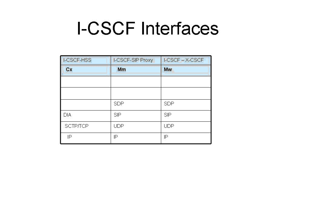
b)   Interrogating CSCF(I- CSCF) interface

 i


As can be seen from above all the interfaces (Cx, Mm and Mw) of the I-CSCF are either UDP/IP or SCTP/TCP/IP.

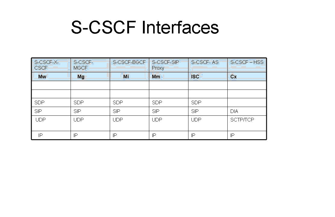
c)   Serving CSCF (S-CSCF) interfaces

The interfaces of the S-CSCF (Mw, Mg, Mi, Mm, ISC and Cx) are all either UDP/IP or SCTP/TCP/IP

s

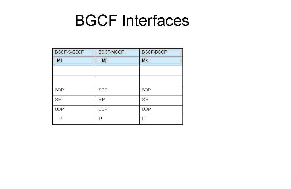
d)   Breakout CSCF (BGCF) interface

The interfaces of the BGCF (Mi, Mj, Mk) are all UDP/IP.

bg

Network elements on the private cloud

The following network elements will be on the private cloud

a)   HSS b) AS

a)   Home Subscriber Service (HSS) interface

The HSS interface (Cx) is DIAMETER/SCTP/TCP over IP.

h

b)   Application Server (AS) Interface

a 

The AS interface ISC is SDP/SIP/UDP over IP.

As can be seen the interfaces the different network elements have towards other elements are over either UDP/IP or TCP/IP.

Hence we can readily see that a cloud deployment of the IMS framework is feasible.

Conclusion

claimtoken-515bdc0894cdb

Thus it can be seen that a cloud based IMS deployment is feasible given the IP interface of the CSCFs, HSS and AS. Key features of the cloud like elasticity and utility style charging will be make the service attractive to the Service providers. A cloud based IMS deployment is truly a great combination for all parties involved namely the subscriber, the Operator and the equipment manufactures. A cloud based deployment will allow the Operator to start with a small customer base and grow as the service becomes popular. Besides the irresistibility of IMS’ high speed data and video applications are bound to capture the subscribers imagination while proving a lot cheaper.

Also see my post on “Envisioning a Software Defined Ip Multimedia System (SD-IMS)

Find me on Google+

Designing a Social Web Portal

Here’s another novel idea of mine, “Designing a Social Web Portal”  that has made it to IP.com (intellectual property).

I have included below the full article in which the Web Portal is re-imagined by adding the social paradigm to a portal.

Abstract

portalThe Social Web Portal, re-imagines the Web Portal using the social paradigm The Social Web Portal is common portal into which all users would login similar to Facebook, Google+ or Twitter. In the Social Web Portal users can choose their family, friends, acquaintances, professional colleagues. Once users are registered in the portal, the Social Web Portal will analyze the click stream history of all the registered users and display the relevant links for each user based on the user’s social circle. Hence in the Social Web Portal each user will get an instantaneous update of relevant,trending URLs/newsitems of his/her social circle based on the click stream data of the social circle in addition to articles of personal interest. Such a portal becomes important in this age of exploding information. The user is completely abreast of all topics of interest of his immediate social circle and the world at large.

Introduction

A large part of our lives is spent on the net. We browse the web for news, stock prices, technology tends, sports updates etc. To do this we typically go to our favorite web sites which are either news aggregators or news curators or we search the web for the required information. This article describes a completely new web browsing experience that is based on the social networking paradigm. This article describes a web portal where the content displayed is based on the browsing preferences of the user, the user’s friends circle, the user’s professional network and the world at large. So the Social Web Portal will display content that is based on the user own preferences, the collective browsing click streams of his/her social network, the user’s professional friends and the world at large. Such a web portal will give the user a snapshot of the kind of news articles that will be of great interest to
him/her. The inclusion of the social paradigm to web browsing provides the user a web browsing experience that is most closely tailored to the user’s taste.

Summary

Web portals like Lycos, Alta-vista, Yahoo, and Excite had their day in the sun early 1990’s. However all this changed with the entry of Google. It had a webpage with a single search bar. With a single stroke Google pushed all the portals to virtual oblivion.

It became obvious to the user that all information was just a “search away”. But much has changed since then. Many pages have been uploaded into the trillion servers that make up the internet. There is so much more information in the worldwide web. News articles, wikis, blogs, tweets, webinars, podcasts, photos, you tube content, social networks etc.

The internet now contains 8.11+ billion pages has more than 1.97 billion users, 266 million websites. We can expect the size to keep growing as the rate of information generation and our thirst for information keeps increasing.

In this world of exploding information the “humble search” will no longer be sufficient. As a user we would like to browse the web in a much more efficient, effective and personalized way. Neither will site aggregators like StumbleUpon, Digg, Reddit or sites which are news curators will be useful. We need to have a smart way to be able to navigate through this information deluge that is personalized to our tastes and to our social circle’s tastes.

We have now entered into an era of social networking where we keep contact with friends on social sites like Facebook, Google+ and with our professional network on LinkedIn and with the world at large on sites like Twitter and Pinterest. These social web sites deliver content based on our connections or our network.

The social web portal delivers content to the portal based on the user’s social network and the user’s social network’s browsing tendencies. It is in this context that it makes great sense to deliver a web portal experience that is based on the user’s personal, family, friend, professional and world browsing
preferences.

Description

Can a Web Portal render content to a single page with topics & news items based on the user’s social circle centered on the user?

The Social Web Portal discusses such a portal for the user which renders content dynamically based on the click stream of the user’s social network. The Social Web Portal will deliver content that has the user’s browsing preferences as the focal center while also displaying the browsing trends of the user’s family, the user’s close friends, the user’s professional colleagues and associates. Finally the portal would also include inputs from what the world at large is interested in and following. The web portal would analyze the key user’s preferences and then create a web portal based on its analysis of
what the user would like to see.

Social Web Portal – Fundamental concept and premise

The Social Web Portal is not a personalized home page in which RSS feeds or inputs from feed aggregators or site aggregators are taken. The Social Web Portal is common portal into which all users would log into similar to Facebook, Google+ or Twitter. All users can choose their friends, acquaintances, professional colleagues in this portal. Once users are registered the click stream history of the all the registered users are continuously updated by the Social Web Portal to a back-end database. Then based on each individual’s social circle the Social Web Portal will perform a statistical analysis of those URLs which were more relevant in the user’s social circle and display these URLs in the user’s page on the Social Web Portal. So when the user logs into the Social Web Portal the webpage will be personalized based on the user’s individual preferences and the collective browsing history of the user’s social circle (friends, colleagues,acquaintances etc).

The Social Web Portal does not take any feeds from existing social networking web sites like Facebook, Google+, Twitter or Youtube. It is independent of these sites. It does not aggregate the feeds from these sites nor does it depend on the social signals from these sites.

The Social Web Portal will generate ‘social signals” independently and completely based on the user’s social circle and the collective browsing history of the user’s social network.

Also the “Social Web Portal” is fundamentally different from link aggregators or a feed aggregators. As mentioned above the Social Web Portal will be based on a statistical analysis of the user network’s browsing history. So regardless of whether a user manually updates a Facebook/Google status, or a user submits a link to a link aggregating web site, the Social Web Portal will analyze the browsing history of the user’s social network and render the portal with the most browsed content.

The collective click stream of the user’s social circle will be analyzed statistically and the sites that have been most visited based on the user’s social circle will be displayed. Hence the user will be aware of the topics of interest of his/her social circle.

The major difference that the Social Web portal has with respect to link aggregators or feed aggregators mentioned above is that the Social Web Portal does not rely on either links submitted by the user’s social circle nor does it depend on the status updates of the user’s network.

The Web page rendered by the Social Web Portal will be based on a statistical ranking of the browsing history of the user’s social circle and also on the relative importance of the friends in the user’s social circle.

Detailed description

The Social Web Portal is based on the collective click stream activity of a user’s family, friends, professional circle and the world at large. This web portal will required to be signed on like any of the social network sites like FB, Google+ or Twitter. The web portal will have a window on the top right corner where the user can send invites, connection requests to his family members, friends and his professional colleagues. The click streams of all those who accept the user’s invite will be used to provide the web browsing experience for the user.

The user can also assign a degree of importance to each of his associations. So while a typical social network site like FB, Google+ or Twitter will provide the status updates of the connections of the user to the user’s updates and include the user’s updates in the connection’s updates, the Social Web Portal will keep track of the click streams of the all the users who have signed into the Social Web Portal. The browsing history of all the users who are registered in the Social Web Portal will be sent to a back-end database for subsequent processing and displaying in the appropriate social circle. Hence as the registered users travel from site to site their browsing history is captured and sent to the back-end database. The click stream history of all the registered users will be continuously updated to a back-end database. It will then render content to each of the individuals in the Social Web Portal
based on the network of that particular user.

The back-end database will be a repository of the browsing click streams of all the users who have signed up for the Social Web Portal. The browsing history of all registered users will be captured and sent to a back-end database, probably using cookies, on a regular basis. These cookies will be analyzed statistically by an application layer over the database which will then display content to a user based on the browsing history of the user’s social circle. Each association in the social circle will be ranked based on a degree of importance assigned by the user.

When a user opens the Social Web Portal the portal will query the back-end database based on the social network that the user has and the degree of importance that the user has for each of his/her connections.

The query will return the overall browsing preferences that are based on the user’s network i.e. the Social Web Portal will render the web page with the aggregate, collective web browsing tendencies of the user’s family, friends, colleagues and friends besides including the user’s own tastes and browsing preferences. So every user will be aware of the common trends and popular items in his/her social circle along with the trending topics in the world at large.

This can be represented in the diagram below

win

Fig 1. Dynamic Window in the Social Web Portal

The rectangle shown in the above window is something that can be tuned by each user for his/ her individual taste. The user can specify how much of the browsing tendencies of friends, family and colleagues he or she would like to include in the Social Web Portal. Based on the user’s taste the content that will be displayed on the user’s Social Web Portal will have appropriate content of the user’s family, friend, colleagues and World

The Social Web Portal for a user can be visualized to be represented as shown below

portal

Fig 2. Snapshot of what each user would see when he logs into the Social Web Portal

As can be seen this Web page will be customized to the user. It will display all the relevant news items and articles of interest for the user. Any user will also be interested to see what people in his/her particular domain are reading. For e.g. a person in finance would like to see specific topics in finance while also being interested in the other relevant news items that he may have missed but may have been read by his/her friends or colleagues.

In other words each user will get a snapshot of information. This information will be tailored to the user based on the individual’s personal preferences, the trending topics in among his family, friends, colleagues, acquaintances and the world at large. So every user will be fully abreast of the popular topics issues in the world without having to individually browse sites. The above figure shows how this snapshot would look for each user.

People also typically like to see if they are up to date with the world on topics. The Social Web Portal will ensure that popular articles automatically bubble up to each and every user.

A diagrammatic representation of the Social Web Portal in action can be represented as below

data

Fig 3. Browsing history maintained in a back-end database and displayed for each user.

In the above figure the click streams of the network of all the users of the Social Web Portal are collected in the distributed database. When a user logs into his Social Web Portal the query will return the overall browsing trends of the user’s family, friends, professional colleagues and the world. Those news items that are popular will be bubbled up to the user along with his or her own preferences. Hence the user will feel connected to his/her network and will have a novel browsing experience.

A diagrammatic representation of the Social Web Portal is shown below

swp1

Fig 4. A schematic of how the personalization happens in the Social Web Portal

In Fig 4 it can be seen that the bottom most layer contains the collective browsing history of all the registered users as they browse different web sites. This click stream will be updated at regular intervals. This browsing history is analyzed statistically to determine the most relevant and popular sites for each user’s social network and then ranked on the degree of importance of each individual in the social circle.

fc

Fig 5. Flow chart for the Social Web Portal

Hence the Social Web Portal will broadly perform the following activities

  • The collective browsing history of all registered users of the Social Web Portal will be sent for analysis to a back-end database
  • The Social Web Portal will render content based on the statistical analysis of the collective click stream activity of a user’s family, friends, professional circle and the world at large
  • The Social Web Portal will render content dynamically based on the statistical ranking of browsing history of user’s social circle
  • A user can configure the order of importance to each of the people in his/her social circle. The Social Web Portal the portal will query the back-end database based on the relative importance of each of the acquaintance of the user and also the statistical weight of “visited sites”
  • The Social Web Portal will render the web page with the “most visited sites” based on the aggregate, collective web browsing tendencies of the user’s family, friends, colleagues and friends besides including the user’s own tastes and browsing preferences.

Benefits

The Social Web Portal will usher in a completely new Web browsing experience. Adding the social paradigm to a user’s browsing experience can have multiple benefits. It will allow each user to know what new articles or items are popular among his or her network. A person can keep abreast of all the trends that are of interest to him/her. The Social Web Portal will be novel experience that will be completely tailored to each and every user.

Find me on Google+

A method for optimal bandwidth usage by auctioning available bandwidth using the OpenFlow protocol

Here is a recent idea of mine that has made it to IP.com (Intellectual Property.com). See link

A method for optimal bandwidth usage by auctioning available bandwidth using the OpenFlow protocol.  Here is the full article from IP.com

In this article I provide some more details to my earlier post – Towards an auction-based internet.

Abstract:
As the data that traverses the internet continues to explode exponentially the issue of a huge bandwidth crunch will be a distinct possibility in the not too distant future. This invention describes a novel technique for auctioning the available bandwidth to users based on bid price, quality of service expected and the type of traffic. The method suggested in this invention is to use the OpenFlow protocol to dynamically allocate bandwidth to users for different flows over a virtualized network infrastructure.

Introduction:
Powerful smartphones, bandwidth-hungry applications, content-rich applications, and increasing user awareness, have together resulted in a virtual explosion of mobile broadband and data usage. There are 2 key drivers behind this phenomenal growth in mobile data. One is the explosion of devices viz. smartphones, tablet PCs, e-readers, laptops with wireless access. The second is video. Over 30% of overall mobile data traffic is video streaming, which is extremely bandwidth hungry. Besides these, new technologies like the “Internet of Things” & “Smart Grids” now have millions and millions of sensors and actuators connected to the internet and contending for scarce bandwidth. In other words there is an enormous data overload happening in the networks of today.
Two key issues of today’s computing infrastructure deal with data latency and the economics of data transfer. Jim Gray (Turing award in 1998) in his paper on “Distributed Computing Economics” tells us that the economics of today’s computing depends on four factors namely computation, networking, database storage and database access. He then equates $1 as follows
One dollar equates to
= 1 $
≈ 1 GB sent over the WAN
≈ 10 Tops (tera CPU operations)
≈ 8 hours of CPU time
≈ 1 GB disk space
≈ 10 M database accesses
≈ 10 TB of disk bandwidth
≈ 10 TB of LAN bandwidth
As can be seen from above breakup, there is a disproportionate contribution by the WAN bandwidth in comparison to the others. In others words while the processing power of CPUs and the storage capacities have multiplied accompanied by dropping prices, the cost of bandwidth has been high. Moreover the available bandwidth is insufficient to handle the explosion of data traffic.
It is claimed that the “cheapest and fastest way to move a Terabyte cross country is sneakernet (i.e. the transfer of electronic information, especially computer files, by physically carrying removable media such as magnetic tape, compact discs, DVDs, USB flash drives, or external drives from one computer to another).
While there has been a tremendous advancement in CPU processing power (CPU horsepower in the range of petaflops) and enormous increases in storage capacity(of the order of petabytes) coupled with dropping prices, there has been no corresponding drop in bandwidth prices in relation to the bandwidth capacity.
It is in this context an auction-based internet makes eminent sense. An auction-based internet would be a business model in which bandwidth would be allocated to different data traffic on the internet based on dynamic bidding by different network elements. Such an approach becomes imperative while considering the economics and latencies involved in data transfer and the emergence of the promising technology known as the OpenFlow protocol. This is further elaborated below

Description

As mentioned in Jim Turing’s paper a key issue that we are going to face in the future has to do with the economics of data transfer and the associated WAN latencies
As can be seen there are 3 distinct issues with the current state of technology
1) There is an exponential increase in data traffic circling the internet. According to a Cisco report the projected increase in data traffic between 2014 and 2015 is of the order of 200 exabytes (10^18)).The internet is thus clogged due to the many bandwidth hungry applications and millions of devices that make the internet
2) WAN latencies and the economics of data transfers are two key issues of the net
3) Service Providers have not found a good way to monetize this data explosion.
Clearly bandwidth is a resource that needs to be utilized judiciously given that there are several contenders for the usage of bandwidth.
Detailed description: This invention suggests a scheme by which internet bandwidth can be auctioned between users based on their bid price, Quality of Service (QoS) required and the type of traffic (video, voice, data, streaming). The energy utility already auctions electricity to the highest bidder. This invention suggests a similar approach to auction scarce bandwidth to competing bidders.
The internet pipes get crowded at different periods of the day, during seasons and during popular sporting events. This invention suggests the need for an intelligent network to price data transfer rates differently depending on the time of the day, the type of traffic and the quality of service required. In this scheme of things the internet will be based on an auction mechanism in which different devices bid for scarce bandwidth based on the urgency, speed and quality of services required.
Such a network can be realized today provided the network and the network elements that constitute the internet implement the OpenFlow protocol.
Software Defined Networks (SDNs) is the new, path breaking innovation in which network traffic can be controlled programmatically through the use of the OpenFlow protocol. SDN is the result of pioneering effort by Stanford University and University of California, Berkeley and is based on the Open Flow Protocol and represents a paradigm shift to the way networking elements operate.

SDNs can be made to dynamically route traffic flows based on decisions in real time. The flow of data packets through the network can be controlled in a programmatic manner through the OpenFlow protocol. In order to dynamically allocate smaller or fatter pipes for different flows, it necessary for the logic in the Flow Controller to be updated dynamically based on the bid price, QoS parameters and the traffic type.

The OpenFlow protocol has a Flow Controller element which can be made to create different flows by manipulating the flow tables of the different network elements. Hence the Flow Controller depending on the bid price, the bandwidth rate and the QoS will auction the different bids and create different flows for different users. The Flow Controller will then update the flow tables of the network elements that will participate to realize this end-to-end flow of traffic for different users.

A typical scenario can be visualized as below

pat1

In the above figure different users bid for available bandwidth. For e.g. User A could bid for A Mbps @ $a/bit for traffic type A, User B could bid for B Mbps @ $b/bit for traffic type B and User C could bid for C Mbps @ $c/bit for traffic type C. The different QoS parameters like delay, throughput, and jitter are all sent in the user requests. The Flow controller receives all these bids with associated parameters and auctions the available bandwidth against the bid prices that the network elements bid for. The Flow Controller then ranks the bids against the most optimal bandwidth allocation that has the highest return.

The Flow Controller can then allocate different bandwidths to the different users based on the bids from the highest to the lowest, quality of service and the type of traffic. Software Defined Networks (SDNs) can then create different flows for across the networks. SDN can create different slices of network elements from end-to–end for each of the different flow requirements.

The Flow Controller can then create these flows and update the flow tables of the network elements based on the allotted speeds for the bid price.

This is shown diagrammatically below

pat2


For e.g. we could assume that a corporate has 3 different flows namely, Immediate, ASAP (As soon as possible) and  price below $x. Based on the upper ceiling for the bid price, the OpenFlow controller will allocate a flow for the immediate traffic of the corporation. For the ASAP flow, the corporate would have requested that the flow be arranged when the bid price falls between a range $a – $b. The OpenFlow Controller will ensure that it can arrange for such a flow. The last type of traffic will be allotted a default flow during non-peak hours. This will require that the OpenFlow controller be able to allocate different flows dynamically based on winning the auction process that happens in this scheme.

Using the OpenFlow paradigm to auction bandwidth

These will be the typical steps that will occur during

  1. Let us assume that it is the period of the day when the usage is at its peak
  2. Let there be 3 users User A, User B and User C who would like to video-conference, video stream and make a voice call respectively
  3. Depending on the urgency and the price that the users can afford these 3 users will bid for a slice of a bandwidth to complete their call
  4. Let user A request A Mbps @ $a/bit for QoS parameters p(a). Let user B request B Mbps @ $b/bit for QoS parameters p(b) and user C request C Mbps @ $c/bit for QoS parameters p(c).
  5. When the Flow Controller receives these requests, based on the available bandwidth at its disposal (assuming it has already used X Mbps for already existing flows) it will normalize these requests and auction them so that it results in the highest bid winning its requested bandwidth slice followed by the ones lower than it. If a user does not qualify the auction the user will have a bid at a later time according to some algorithm. Let us assume that user A and user C win their bids
  6. The Flow Controller will now algorithmically decide the contents of the flow tables of the intervening network elements and will accordingly populate these flow tables
  7. The flows for User A and User C are now in progress.
  8. The Flow Controller will accept bids whenever there is spare bandwidth that can be put up for auction.

As can be seen such a mechanism will result in a varying price for bandwidth with the highest value during peak periods and lower values during off-peak periods.

Benefits: The current protocols of the internet of today namely IntServ, DiffServ allocate pipes based on the traffic type & class which is static once allocated. This strategy enables OpenFlow to dynamically adjust the traffic flows based on the current bid price prevailing in that part of the network. Moreover the usage of OpenFlow protocol can generate a lot more granualar flow types.

The ability of the OpenFlow protocol to be able to dynamically allocate different flows will once and for all solve the problem of being able to monetize mobile and fixed line data This will be a win-win for both the Service Providers and the consumer. The Service Provider will be able to get a ROI for the infrastructure based on the traffic flowing through his network. Users can decide the type of service they are interested and choose appropriately. The consumer rather than paying a fixed access charge could have a smaller charge because of low bandwidth usage.

Conclusion: An auction-based internet is a worthwhile business model to pursue. The ability to route traffic dynamically based on an auction mechanism in the internet enables the internet infrastructure to be utilized optimally. It will serve the dual purpose of solving traffic congestion, as highest bidders will get the pipe but will also monetize data traffic based on its importance to the end user.

Find me on Google+