Introducing QCSimulator: A 5-qubit quantum computing simulator in R

Introduction

My 5-qubit Quantum Computing Simulator,QCSimulator, is finally ready, and here it is! I have been able to successfully complete this simulator by working through a fair amount of material. To a large extent, the simulator is easy, if one understands how to solve the quantum circuit. However the theory behind quantum computing itself, is quite formidable, and I hope to scale this mountain over a period of time.

QCSimulator is now on CRAN!!!

The code for the QCSimulator package is also available at Github QCSimulator. This post has also been published at Rpubs as QCSimulator and can be downloaded as a PDF document at QCSimulator.pdf

Disclaimer: This article represents the author’s viewpoint only and doesn’t necessarily represent IBM’s positions, strategies or opinions

install.packages("QCSimulator")
library(QCSimulator)
library(ggplot2)

1. Initialize the environment and set global variables

Here I initialize the environment with global variables and then display a few of them.

rm(list=ls())
#Call the init function to initialize the environment and create global variables
init()

# Display some of global variables in environment
ls()
##  [1] "I16"     "I2"      "I4"      "I8"      "q0_"     "q00_"    "q000_"  
##  [8] "q0000_"  "q00000_" "q00001_" "q0001_"  "q00010_" "q00011_" "q001_"  
## [15] "q0010_"  "q00100_" "q00101_" "q0011_"  "q00110_" "q00111_" "q01_"   
## [22] "q010_"   "q0100_"  "q01000_" "q01001_" "q0101_"  "q01010_" "q01011_"
## [29] "q011_"   "q0110_"  "q01100_" "q01101_" "q0111_"  "q01111_" "q1_"    
## [36] "q10_"    "q100_"   "q1000_"  "q10000_" "q10001_" "q1001_"  "q10010_"
## [43] "q10011_" "q101_"   "q1010_"  "q10100_" "q10101_" "q1011_"  "q10110_"
## [50] "q10111_" "q11_"    "q110_"   "q1100_"  "q11000_" "q11001_" "q1101_" 
## [57] "q11010_" "q11011_" "q111_"   "q1110_"  "q11100_" "q11101_" "q1111_" 
## [64] "q11110_" "q11111_"
#1. 2 x 2 Identity matrix 
I2
##      [,1] [,2]
## [1,]    1    0
## [2,]    0    1
#2. 8 x 8 Identity matrix 
I8
##      [,1] [,2] [,3] [,4] [,5] [,6] [,7] [,8]
## [1,]    1    0    0    0    0    0    0    0
## [2,]    0    1    0    0    0    0    0    0
## [3,]    0    0    1    0    0    0    0    0
## [4,]    0    0    0    1    0    0    0    0
## [5,]    0    0    0    0    1    0    0    0
## [6,]    0    0    0    0    0    1    0    0
## [7,]    0    0    0    0    0    0    1    0
## [8,]    0    0    0    0    0    0    0    1
#3. Qubit |00>
q00_
##      [,1]
## [1,]    1
## [2,]    0
## [3,]    0
## [4,]    0
#4. Qubit |010>
q010_
##      [,1]
## [1,]    0
## [2,]    0
## [3,]    1
## [4,]    0
## [5,]    0
## [6,]    0
## [7,]    0
## [8,]    0
#5. Qubit |0100>
q0100_
##       [,1]
##  [1,]    0
##  [2,]    0
##  [3,]    0
##  [4,]    0
##  [5,]    1
##  [6,]    0
##  [7,]    0
##  [8,]    0
##  [9,]    0
## [10,]    0
## [11,]    0
## [12,]    0
## [13,]    0
## [14,]    0
## [15,]    0
## [16,]    0
#6. Qubit 10010
q10010_
##       [,1]
##  [1,]    0
##  [2,]    0
##  [3,]    0
##  [4,]    0
##  [5,]    0
##  [6,]    0
##  [7,]    0
##  [8,]    0
##  [9,]    0
## [10,]    0
## [11,]    0
## [12,]    0
## [13,]    0
## [14,]    0
## [15,]    0
## [16,]    0
## [17,]    0
## [18,]    0
## [19,]    1
## [20,]    0
## [21,]    0
## [22,]    0
## [23,]    0
## [24,]    0
## [25,]    0
## [26,]    0
## [27,]    0
## [28,]    0
## [29,]    0
## [30,]    0
## [31,]    0
## [32,]    0

The QCSimulator implements the following gates

  1. Pauli X,Y,Z, S,S’, T, T’ gates
  2. Rotation , Hadamard,CSWAP,Toffoli gates
  3. 2,3,4,5 qubit CNOT gates e.g CNOT2_01,CNOT3_20,CNOT4_13 etc
  4. Toffoli State,SWAPQ0Q1

2. To display the unitary matrix of gates

To check the unitary matrix of gates, we need to pass the appropriate identity matrix as an argument. Hence below the qubit gates require a 2 x 2 unitary matrix and the 2 & 3 qubit CNOT gates require a 4 x 4 and 8 x 8 identity matrix respectively

PauliX(I2)
##      [,1] [,2]
## [1,]    0    1
## [2,]    1    0
Hadamard(I2)
##           [,1]       [,2]
## [1,] 0.7071068  0.7071068
## [2,] 0.7071068 -0.7071068
S1Gate(I2)
##      [,1] [,2]
## [1,] 1+0i 0+0i
## [2,] 0+0i 0-1i
CNOT2_10(I4)
##      [,1] [,2] [,3] [,4]
## [1,]    1    0    0    0
## [2,]    0    0    0    1
## [3,]    0    0    1    0
## [4,]    0    1    0    0
CNOT3_20(I8)
##      [,1] [,2] [,3] [,4] [,5] [,6] [,7] [,8]
## [1,]    1    0    0    0    0    0    0    0
## [2,]    0    0    0    0    0    1    0    0
## [3,]    0    0    1    0    0    0    0    0
## [4,]    0    0    0    0    0    0    0    1
## [5,]    0    0    0    0    1    0    0    0
## [6,]    0    1    0    0    0    0    0    0
## [7,]    0    0    0    0    0    0    1    0
## [8,]    0    0    0    1    0    0    0    0

3. Compute the inner product of vectors

For example of phi = 1/2|0> + sqrt(3)/2|1> and si= 1/sqrt(2)(10> + |1>) then the inner product is the dot product of the vectors

phi = matrix(c(1/2,sqrt(3)/2),nrow=2,ncol=1)
si = matrix(c(1/sqrt(2),1/sqrt(2)),nrow=2,ncol=1)
angle= innerProduct(phi,si)
cat("Angle between vectors is:",angle)
## Angle between vectors is: 15

4. Compute the dagger function for a gate

The gate dagger computes and displays the transpose of the complex conjugate of the matrix

TGate(I2)
##      [,1]                 [,2]
## [1,] 1+0i 0.0000000+0.0000000i
## [2,] 0+0i 0.7071068+0.7071068i
GateDagger(TGate(I2))
##      [,1]                 [,2]
## [1,] 1+0i 0.0000000+0.0000000i
## [2,] 0+0i 0.7071068-0.7071068i

5. Invoking gates in series

The Quantum gates can be chained by passing each preceding Quantum gate as the argument. The final gate in the chain will have the qubit or the identity matrix passed to it.

# Call in reverse order
# Superposition states
# |+> state
Hadamard(q0_)
##           [,1]
## [1,] 0.7071068
## [2,] 0.7071068
# |-> ==> H x Z 
PauliZ(Hadamard(q0_))
##            [,1]
## [1,]  0.7071068
## [2,] -0.7071068
# (+i) Y ==> H x  S 
 SGate(Hadamard(q0_))
##                      [,1]
## [1,] 0.7071068+0.0000000i
## [2,] 0.0000000+0.7071068i
# (-i)Y ==> H x S1
 S1Gate(Hadamard(q0_))
##                      [,1]
## [1,] 0.7071068+0.0000000i
## [2,] 0.0000000-0.7071068i
# Q1 -- TGate- Hadamard
Q1 = Hadamard(TGate(I2))

6. More gates in series

TGate of depth 2

The Quantum circuit for a TGate of Depth 2 is

Q0 — Hadamard-TGate-Hadamard-TGate-SGate-Measurement as shown in IBM’s Quantum Experience Composer

Untitled

Implementing the quantum gates in series in reverse order we have

# Invoking this in reverse order we get
a = SGate(TGate(Hadamard(TGate(Hadamard(q0_)))))
result=measurement(a)

plotMeasurement(result)

fig0-1

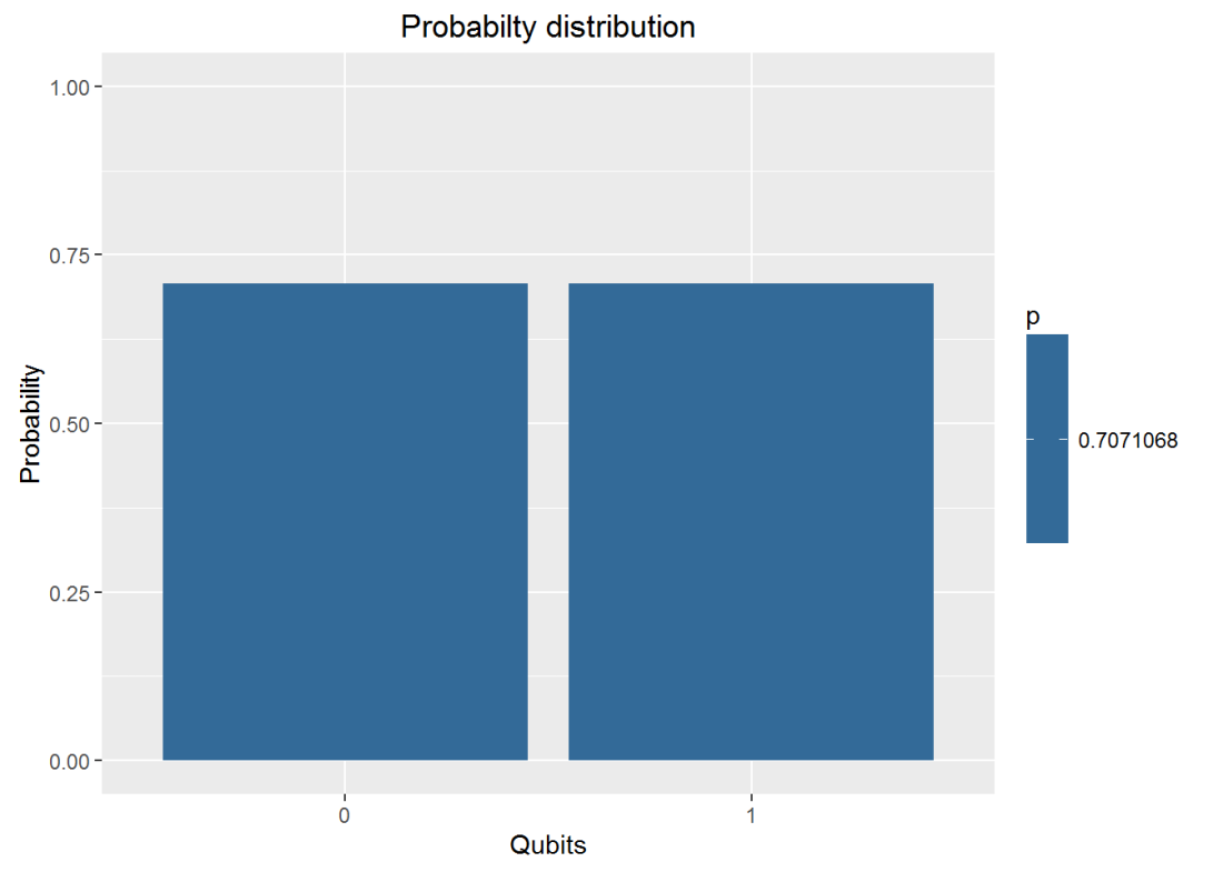
7. Invoking gates in parallel

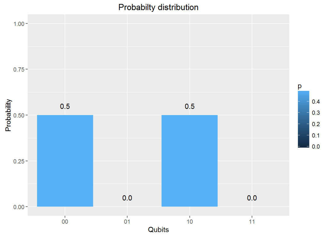
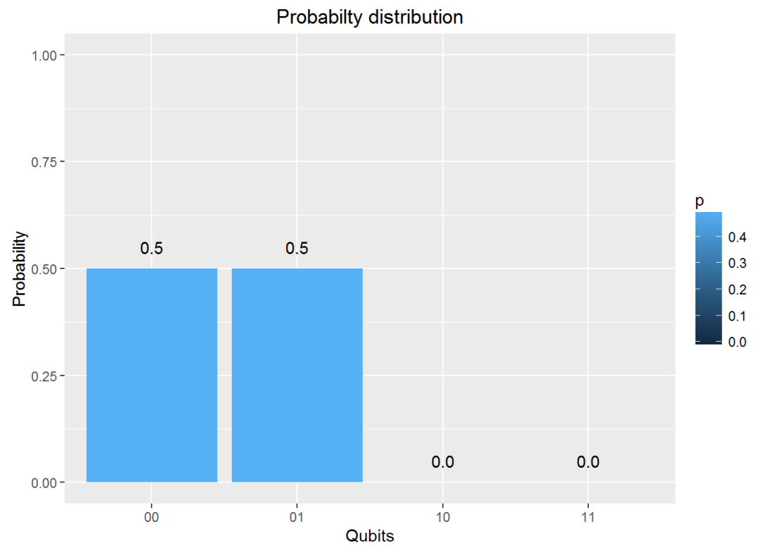
To obtain the results of gates in parallel we have to take the Tensor Product Note:In the TensorProduct invocation the Identity matrix is passed as an argument to get the unitary matrix of the gate. Q0 – Hadamard-Measurement Q1 – Identity- Measurement

# 
a = TensorProd(Hadamard(I2),I2)
b = DotProduct(a,q00_)
plotMeasurement(measurement(b))

fig1-1

a = TensorProd(PauliZ(I2),Hadamard(I2))
b = DotProduct(a,q00_)
plotMeasurement(measurement(b))

fig1-2

8. Measurement

The measurement of a Quantum circuit can be obtained using the measurement function. Consider the following Quantum circuit
Q0 – H-T-H-T-S-H-T-H-T-H-T-H-S-Measurement where H – Hadamard gate, T – T Gate and S- S Gate

a = SGate(Hadamard(TGate(Hadamard(TGate(Hadamard(TGate(Hadamard(SGate(TGate(Hadamard(TGate(Hadamard(I2)))))))))))))
measurement(a)
##          0        1
## v 0.890165 0.109835

9. Plot measurement

Using the same example as above Q0 – H-T-H-T-S-H-T-H-T-H-T-H-S-Measurement where H – Hadamard gate, T – T Gate and S- S Gate we can plot the measurement

a = SGate(Hadamard(TGate(Hadamard(TGate(Hadamard(TGate(Hadamard(SGate(TGate(Hadamard(TGate(Hadamard(I2)))))))))))))
result = measurement(a)
plotMeasurement(result)

fig2-1

10. Evaluating a Quantum Circuit

The above procedures for evaluating a quantum gates in series and parallel can be used to evalute more complex quantum circuits where the quantum gates are in series and in parallel.

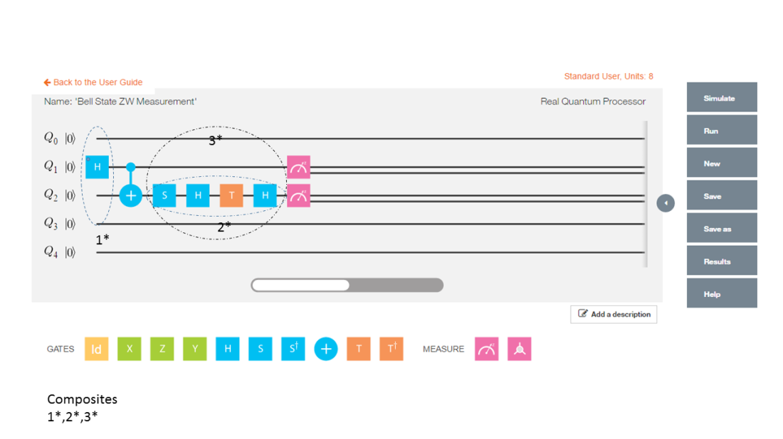
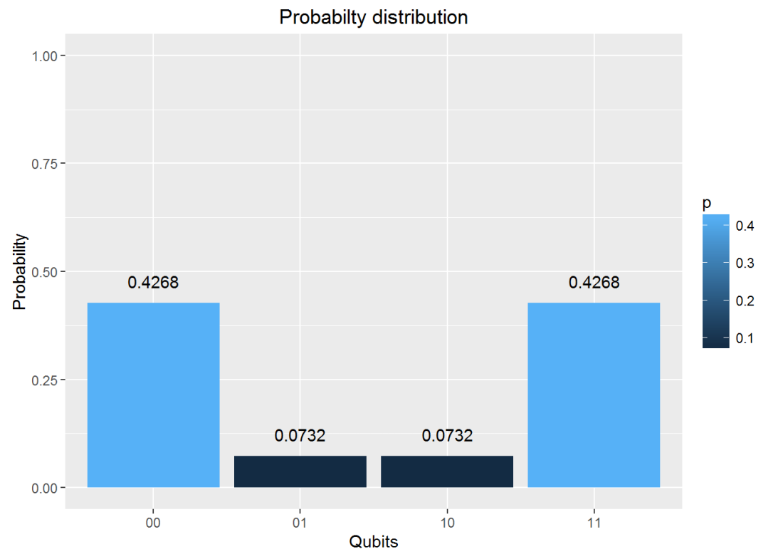
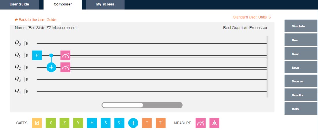
Here is an evaluation of one such circuit, the Bell ZQ state using the QCSimulator (from IBM’s Quantum Experience)

pic3

# 1st composite
a = TensorProd(Hadamard(I2),I2)
# Output of CNOT
b = CNOT2_01(a)
# 2nd series
c=Hadamard(TGate(Hadamard(SGate(I2))))
#3rd composite
d= TensorProd(I2,c)
# Output of 2nd composite
e = DotProduct(b,d)
#Action of quantum circuit on |00>
f = DotProduct(e,q00_)
result= measurement(f)
plotMeasurement(result)

fig3-1

11. Toffoli State

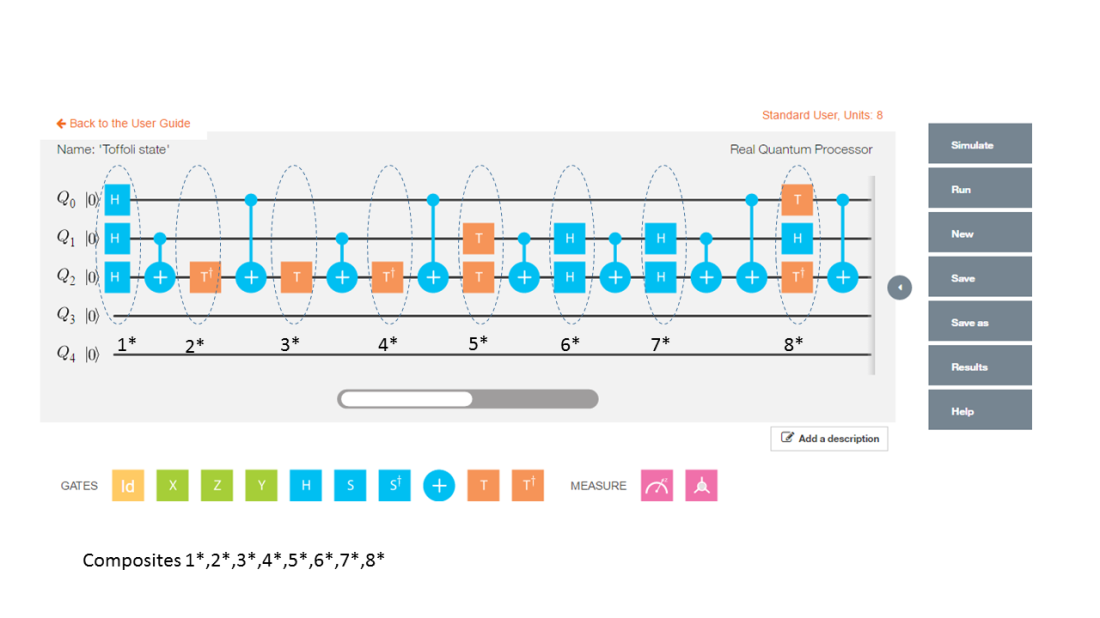
This circuit for this comes from IBM’s Quantum Experience. This circuit is available in the package. This is how the state was constructed. This circuit is shown below

pic2

The implementation of the above circuit in QCSimulator is as below

  # Computation of the Toffoli State
    H=1/sqrt(2) * matrix(c(1,1,1,-1),nrow=2,ncol=2)
    I=matrix(c(1,0,0,1),nrow=2,ncol=2)

    # 1st composite
    # H x H x H
    a = TensorProd(TensorProd(H,H),H)
    # 1st CNOT
    a1= CNOT3_12(a)

    # 2nd composite
    # I x I x T1Gate
    b = TensorProd(TensorProd(I,I),T1Gate(I))
    b1 = DotProduct(b,a1)
    c = CNOT3_02(b1)

    # 3rd composite
    # I x I x TGate
    d = TensorProd(TensorProd(I,I),TGate(I))
    d1 = DotProduct(d,c)
    e = CNOT3_12(d1)

    # 4th composite
    # I x I x T1Gate
    f = TensorProd(TensorProd(I,I),T1Gate(I))
    f1 = DotProduct(f,e)
    g = CNOT3_02(f1)

    #5th composite
    # I x T x T
    h = TensorProd(TensorProd(I,TGate(I)),TGate(I))
    h1 = DotProduct(h,g)
    i = CNOT3_12(h1)

    #6th composite
    # I x H x H
    j = TensorProd(TensorProd(I,Hadamard(I)),Hadamard(I))
    j1 = DotProduct(j,i)
    k = CNOT3_12(j1)

    # 7th composite
    # I x H x H
    l = TensorProd(TensorProd(I,Hadamard(I)),Hadamard(I))
    l1 = DotProduct(l,k)
    m = CNOT3_12(l1)
    n = CNOT3_02(m)

    #8th composite
    # T x H x T1
    o = TensorProd(TensorProd(TGate(I),Hadamard(I)),T1Gate(I))
    o1 = DotProduct(o,n)
    p = CNOT3_02(o1)
    result = measurement(p)
    plotMeasurement(result)

fig4-1

12. GHZ YYX measurement

Here is another Quantum circuit, namely the entangled GHZ YYX state. This is

pic1

and is implemented in QCSimulator as

# Composite 1
a = TensorProd(TensorProd(Hadamard(I2),Hadamard(I2)),PauliX(I2))
b= CNOT3_12(a)
c= CNOT3_02(b)
# Composite 2
d= TensorProd(TensorProd(Hadamard(I2),Hadamard(I2)),Hadamard(I2))
e= DotProduct(d,c)
#Composite 3
f= TensorProd(TensorProd(S1Gate(I2),S1Gate(I2)),Hadamard(I2))
g= DotProduct(f,e)
#Composite 4
i= TensorProd(TensorProd(Hadamard(I2),Hadamard(I2)),I2)
j = DotProduct(i,g)
result=measurement(j)
plotMeasurement(result)

fig5-1

Conclusion

The 5 qubit Quantum Computing Simulator is now fully functional. I hope to add more gates and functionality in the months to come.

Feel free to install the package from Github and give it a try.

Disclaimer: This article represents the author’s viewpoint only and doesn’t necessarily represent IBM’s positions, strategies or opinions

References

  1. IBM’s Quantum Experience
  2. Quantum Computing in Python by Dr. Christine Corbett Moran
  3. Lecture notes-1
  4. Lecture notes-2
  5. Quantum Mechanics and Quantum Computationat edX- UC, Berkeley

My other posts on Quantum Computing

  1. Venturing into IBM’s Quantum Experience 2.Going deeper into IBM’s Quantum Experience!
  2. A primer on Qubits, Quantum gates and Quantum Operations
  3. Exploring Quantum Gate operations with QCSimulator
  4. Taking a closer look at Quantum gates and their operations

You may also like
For more posts on other topics like Cloud Computing, IBM Bluemix, Distributed Computing, OpenCV, R, cricket please check my Index of posts

Taking a closer look at Quantum gates and their operations

This post is a continuation of my earlier post ‘Exploring Quantum gate operations with QCSimulator’. Here I take a closer look at more quantum gates and their operations, besides implementing these new gates in my Quantum Computing simulator, the  QCSimulator in R.

Disclaimer: This article represents the author’s viewpoint only and doesn’t necessarily represent IBM’s positions, strategies or opinions

In  quantum circuits, gates  are unitary matrices which operate on 1,2 or 3 qubit systems which are represented as below

1 qubit
|0> = \begin{pmatrix}1\\0\end{pmatrix} and |1> = \begin{pmatrix}0\\1\end{pmatrix}

2 qubits
|0> \otimes |0> = \begin{pmatrix}1\\ 0\\ 0\\0\end{pmatrix}
|0> \otimes |1> = \begin{pmatrix}0\\ 1\\ 0\\0\end{pmatrix}
|1> \otimes |o> = \begin{pmatrix}0\\ 0\\ 1\\0\end{pmatrix}
|1> \otimes |1> = \begin{pmatrix}0\\ 0\\ 0\\1\end{pmatrix}

3 qubits
|0> \otimes |0> \otimes |0> = \begin{pmatrix}1\\ 0\\0\\ 0\\ 0\\0\\ 0\\0\end{pmatrix}
|0> \otimes |0> \otimes |1> = \begin{pmatrix}0\\ 1\\0\\ 0\\ 0\\0\\ 0\\0\end{pmatrix}
|0> \otimes |1> \otimes |0> = \begin{pmatrix}0\\ 0\\1\\ 0\\ 0\\0\\ 0\\0\end{pmatrix}


|1> \otimes |1> \otimes |1> = \begin{pmatrix}0\\ 0\\0\\ 0\\ 0\\0\\ 0\\1\end{pmatrix}
Hence single qubit is represented as 2 x 1 matrix, 2 qubit as 4 x 1 matrix and 3 qubit as 8 x 1 matrix

1) Composing Quantum gates in series
When quantum gates are connected in a series. The overall effect of the these quantum gates in series is obtained my taking the dot product of the unitary gates in reverse. For e.g.
Untitled

In the following picture the effect of the quantum gates A,B,C is the dot product of the gates taken reverse order
result = C . B . A

This overall action of the 3 quantum gates can be represented by a single ‘transfer’ matrix which is the dot product of the gates
Untitled

If we had a Pauli X followed by a Hadamard gate the combined effect of these gates on the inputs can be deduced by constructing a truth table

Input Pauli X – Output A’ Hadamard – Output B
|0> |1> 1/√2(|0>  – |1>)
|1> |0> 1/√2(|0>  + |1>)

Or

|0> -> 1/√2(|0>  – |1>)
|1> -> 1/√2(|0>  + |1>)
which is
\begin{pmatrix}1\\0\end{pmatrix}  ->1/√2 \begin{pmatrix}1\\0\end{pmatrix}\begin{pmatrix}0\\1\end{pmatrix} = 1/√2  \begin{pmatrix}1\\-1\end{pmatrix}
\begin{pmatrix}0\\1\end{pmatrix}  ->1/√2 \begin{pmatrix}1\\0\end{pmatrix} + \begin{pmatrix}0\\1\end{pmatrix} = 1/√2  \begin{pmatrix}1\\1\end{pmatrix}
Therefore the ‘transfer’ matrix can be written as
T = 1/√2 \begin{pmatrix}1 & 1\\ -1 & 1\end{pmatrix}

2)Quantum gates in parallel
When quantum gates are in parallel then the composite effect of the gates can be obtained by taking the tensor product of the quantum gates.
Untitled

If we consider the combined action of a Pauli X gate and a Hadamard gate in parallel
Untitled

A B A’ B’
|0> |0> |1> 1/√2(|0>  + |1>)
|0> |1> |1> 1/√2(|0>  – |1>)
|1> |0> |0> 1/√2(|0>  + |1>)
|1> |1> |0> 1/√2(|0>  – |1>)

Or

|00> => |1> \otimes 1/√2(|0>  + |1>) = 1/√2 (|10> + |11>)
|01> => |1> \otimes 1/√2(|0>  – |1>) = 1/√2 (|10> – |11>)
|10> => |0> \otimes 1/√2(|0>  + |1>) = 1/√2 (|00> + |01>)
|11> => |0> \otimes 1/√2(|0>  – |1>) = 1/√2 (|10> – |11>)

|00> = \begin{pmatrix}1\\ 0\\ 0\\0\end{pmatrix} =>1/√2\begin{pmatrix} 0\\ 0\\ 1\\ 1\end{pmatrix}
|01> = \begin{pmatrix}0\\ 1\\ 0\\0\end{pmatrix} =>1/√2\begin{pmatrix} 0\\ 0\\ 1\\ -1\end{pmatrix}
|10> = \begin{pmatrix}0\\ 0\\ 1\\0\end{pmatrix} =>1/√2\begin{pmatrix} 1\\ 0\\ 1\\ -1\end{pmatrix}
|11> = \begin{pmatrix}0\\ 0\\ 0\\1\end{pmatrix} =>1/√2\begin{pmatrix} 1\\ 0\\ -1\\ -1\end{pmatrix}

Here are more Quantum gates
a) Rotation gate
U = \begin{pmatrix}cos\theta & -sin\theta\\ sin\theta & cos\theta\end{pmatrix}

b) Toffoli gate
The Toffoli gate flips the 3rd qubit if the 1st and 2nd qubit are |1>

Toffoli gate
Input Output
|000> |000>
|001> |001>
|010> |010>
|011> |011>
|100> |100>
|101> |101>
|110> |111>
|111> |110>

c) Fredkin gate
The Fredkin gate swaps the 2nd and 3rd qubits if the 1st qubit is |1>

Fredkin gate
Input Output
|000> |000>
|001> |001>
|010> |010>
|011> |011>
|100> |100>
|101> |110>
|110> |101>
|111> |111>

d) Controlled U gate
A controlled U gate can be represented as
controlled U = \begin{pmatrix}1 & 0 & 0 & 0\\ 0 &1  &0  & 0\\ 0 &0  &u11  &u12 \\ 0 & 0 &u21  &u22 \end{pmatrix}   – (A)
where U =  \begin{pmatrix}u11 &u12 \\ u21 & u22\end{pmatrix}

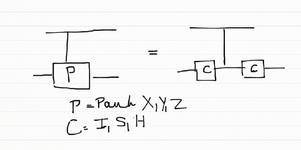
e) Controlled Pauli gates
Controlled Pauli gates are created based on the following identities. The CNOT gate is a controlled Pauli X gate where controlled U is a Pauli X gate and matches the CNOT unitary matrix. Pauli gates can be constructed using

a) H x X x H = Z    &
H x H = I

b) S x X x S1
S x S1 = I

the controlled Pauli X, Y , Z are contructed using the CNOT for the controlled X in the above identities
In general a controlled Pauli gate can be created as below
Untitled

f) CPauliX
Here C is the 2 x2  Identity matrix. Simulating this in my QCSimulator
CPauliX I=matrix(c(1,0,0,1),nrow=2,ncol=2)
# Compute 1st composite
a = TensorProd(I,I)
b = CNOT2_01(a)
# Compute 1st composite
c = TensorProd(I,I)
#Take dot product
d = DotProduct(c,b)
#Take dot product with qubit
e = DotProduct(d,q)
e
}

Implementing the above with I, S, H gives Pauli X, Y and Z as seen below

library(QCSimulator)
I4=matrix(c(1,0,0,0,
            0,1,0,0,
            0,0,1,0,
            0,0,0,1),nrow=4,ncol=4)

#Controlled Pauli X
CPauliX(I4)
##      [,1] [,2] [,3] [,4]
## [1,]    1    0    0    0
## [2,]    0    1    0    0
## [3,]    0    0    0    1
## [4,]    0    0    1    0
#Controlled Pauli Y
CPauliY(I4)
##      [,1] [,2] [,3] [,4]
## [1,] 1+0i 0+0i 0+0i 0+0i
## [2,] 0+0i 1+0i 0+0i 0+0i
## [3,] 0+0i 0+0i 0+0i 0-1i
## [4,] 0+0i 0+0i 0+1i 0+0i
#Controlled Pauli Z
CPauliZ(I4)
##      [,1] [,2] [,3] [,4]
## [1,]    1    0    0    0
## [2,]    0    1    0    0
## [3,]    0    0    1    0
## [4,]    0    0    0   -1

g) CSWAP gate

Untitled

q00=matrix(c(1,0,0,0),nrow=4,ncol=1)
q01=matrix(c(0,1,0,0),nrow=4,ncol=1)
q10=matrix(c(0,0,1,0),nrow=4,ncol=1)
q11=matrix(c(0,0,0,1),nrow=4,ncol=1)
CSWAP(q00)
##      [,1]
## [1,]    1
## [2,]    0
## [3,]    0
## [4,]    0
#Swap qubits 
CSWAP(q01)
##      [,1]
## [1,]    0
## [2,]    0
## [3,]    1
## [4,]    0
#Swap qubits 
CSWAP(q10)
##      [,1]
## [1,]    0
## [2,]    1
## [3,]    0
## [4,]    0
CSWAP(q11)
##      [,1]
## [1,]    0
## [2,]    0
## [3,]    0
## [4,]    1

h) Toffoli state
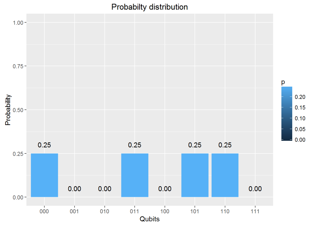
The Toffoli state creates a 3 qubit entangled state 1/2(|000> + |001> + |100> + |111>)
Untitled

Simulating the Toffoli state in IBM Quantum Experience we get
Untitled

h) Implementation of Toffoli state in QCSimulator 

#ToffoliState 
    # Computation of the Toffoli State
    H=1/sqrt(2) * matrix(c(1,1,1,-1),nrow=2,ncol=2)
    I=matrix(c(1,0,0,1),nrow=2,ncol=2)

    # 1st composite
    # H x H x H
    a = TensorProd(TensorProd(H,H),H)
    # 1st CNOT
    a1= CNOT3_12(a)

    # 2nd composite
    # I x I x T1Gate
    b = TensorProd(TensorProd(I,I),T1Gate(I))
    b1 = DotProduct(b,a1)
    c = CNOT3_02(b1)

    # 3rd composite
    # I x I x TGate
    d = TensorProd(TensorProd(I,I),TGate(I))
    d1 = DotProduct(d,c)
    e = CNOT3_12(d1)

    # 4th composite
    # I x I x T1Gate
    f = TensorProd(TensorProd(I,I),T1Gate(I))
    f1 = DotProduct(f,e)
    g = CNOT3_02(f1)

    #5th composite
    # I x T x T
    h = TensorProd(TensorProd(I,TGate(I)),TGate(I))
    h1 = DotProduct(h,g)
    i = CNOT3_12(h1)

    #6th composite
    # I x H x H
    j = TensorProd(TensorProd(I,Hadamard(I)),Hadamard(I))
    j1 = DotProduct(j,i)
    k = CNOT3_12(j1)

    # 7th composite
    # I x H x H
    l = TensorProd(TensorProd(I,Hadamard(I)),Hadamard(I))
    l1 = DotProduct(l,k)
    m = CNOT3_12(l1)
    n = CNOT3_02(m)

    #8th composite
    # T x H x T1
    o = TensorProd(TensorProd(TGate(I),Hadamard(I)),T1Gate(I))
    o1 = DotProduct(o,n)
    p = CNOT3_02(o1)
    result = measurement(p)
    plotMeasurement(result)

a-1
The measurement is identical to the that of IBM Quantum Experience

Conclusion:  This post looked at more Quantum gates. I have implemented all the gates in my QCSimulator which I hope to release in a couple of months.

Disclaimer: This article represents the author’s viewpoint only and doesn’t necessarily represent IBM’s positions, strategies or opinions

References
1. http://www1.gantep.edu.tr/~koc/qc/chapter4.pdf
2. http://iontrap.umd.edu/wp-content/uploads/2016/01/Quantum-Gates-c2.pdf
3. https://quantumexperience.ng.bluemix.net/

Also see
1.  Venturing into IBM’s Quantum Experience
2. Going deeper into IBM’s Quantum Experience!
3.  A primer on Qubits, Quantum gates and Quantum Operations
4. Exploring Quantum gate operations with QCSimulator

Take a look at my other posts at
1. Index of posts
Exploring Quantum Gate operations with QCSimulator

Introduction: Ever since I was initiated into Quantum Computing, through IBM’s Quantum Experience I have been hooked. My initial encounter with domain made me very excited and all wound up. The reason behind this, I think, is because there is an air of mystery around ‘Quantum’ anything.  After my early rush with the Quantum Experience, I have deliberately slowed down to digest the heady stuff.

This post also includes my early prototype of a Quantum Computing Simulator( QCSimulator) which I am creating in R. I hope to have a decent Quantum Computing simulator available, in the next couple of months. The ideas for this simulator are based on IBM’s Quantum Experience and the lectures on Quantum Mechanics and Quantum Computation by Prof Umesh Vazirani from University of California at Berkeley at edX. This calls to this simulator have been included in R Markdown file and has been published at RPubs as Quantum Computing Simulator

Disclaimer: This article represents the author’s viewpoint only and doesn’t necessarily represent IBM’s positions, strategies or opinions

In this post I explore quantum gate operations

A) Quantum Gates
Quantum gates are represented as a n x n unitary matrix. In mathematics, a complex square matrix U is unitary if its conjugate transpose Uǂ is also its inverse – that is, if
U ǂU =U U ǂ=I

a) Clifford Gates
The following gates are known as Clifford Gates and are represented as the unitary matrix below

1. Pauli X
\begin{pmatrix}0&1\\1&0\end{pmatrix}

2.Pauli Y
\begin{pmatrix}0&-i\\i&0\end{pmatrix}

3. Pauli Z
\begin{pmatrix}1&0\\0&-1\end{pmatrix}

4. Hadamard
1/√2 \begin{pmatrix}1 & 1\\ 1 & -1\end{pmatrix}

5. S Gate
\begin{pmatrix}1 & 0\\ 0 & i\end{pmatrix}

6. S1 Gate
\begin{pmatrix}1 & 0\\ 0 & -i\end{pmatrix}

7. CNOT
\begin{pmatrix}1 & 0 & 0 &0 \\ 0 & 1 & 0 &0 \\  0& 0 &  0&1 \\ 0 & 0 & 1 & 0\end{pmatrix}

b) Non-Clifford Gate
The following are the non-Clifford gates
1. Toffoli Gate
T = \begin{pmatrix}1 & 0\\ 0 & e^{^{i\prod /4}}\end{pmatrix}

2. Toffoli1 Gate
T1 = \begin{pmatrix}1 & 0\\ 0 & e^{^{-i\prod /4}}\end{pmatrix}

B) Evolution of a 1 qubit Quantum System
The diagram below shows how a 1 qubit system evolves on the application of Quantum Gates.

Untitled

C) Evolution of a 2 Qubit  System
The following diagram depicts the evolution of a 2 qubit system. The 4 different maximally entangled states can be obtained by using a Hadamard and a CNOT gate to |00>, |01>, |10> & |11> resulting in the entangled states  Φ+, Ψ+, Φ, Ψrespectively

Untitled

D) Verifying Unitary’ness
XXǂ = XǂX= I
TTǂ = TǂT=I
SSǂ = SǂS=I
The Uǂ  function in the simulator is
Uǂ = GateDagger(U)

E) A look at some Simulator functions
The unitary functions for the Clifford and non-Clifford gates have been implemented functions. The unitary functions can be chained together by invoking each successive Gate as argument to the function.

1. Creating the dagger function
HDagger = GateDagger(Hadamard)
HDagger x Hadamard
TDagger = GateDagger(TGate)
TDagger x TGate

H
##           [,1]       [,2]
## [1,] 0.7071068  0.7071068
## [2,] 0.7071068 -0.7071068
HDagger = GateDagger(H)
HDagger
##           [,1]       [,2]
## [1,] 0.7071068  0.7071068
## [2,] 0.7071068 -0.7071068
HDagger %*% H
##      [,1] [,2]
## [1,]    1    0
## [2,]    0    1
T
##      [,1]                 [,2]
## [1,] 1+0i 0.0000000+0.0000000i
## [2,] 0+0i 0.7071068+0.7071068i
TDagger = GateDagger(T)
TDagger
##      [,1]                 [,2]
## [1,] 1+0i 0.0000000+0.0000000i
## [2,] 0+0i 0.7071068-0.7071068i
TDagger %*% T
##      [,1] [,2]
## [1,] 1+0i 0+0i
## [2,] 0+0i 1+0i

2. Angle between 2 vectors – Inner product
The angle between 2 vectors can be obtained by taking the inner product between the vectors

#1. a is the diagonal vector 1/2 |0> + 1/2 |1> and b = q0 = |0>
diagonal <-  matrix(c(1/sqrt(2),1/sqrt(2)),nrow=2,ncol=1)
q0=matrix(c(1,0),nrow=2,ncol=1)
innerProduct(diagonal,q0)
##      [,1]
## [1,]   45
#2. a = 1/2|0> + sqrt(3)/2|1> and  b= 1/sqrt(2) |0> + 1/sqrt(2) |1>
a = matrix(c(1/2,sqrt(3)/2),nrow=2,ncol=1)
b = matrix(c(1/sqrt(2),1/sqrt(2)),nrow=2,ncol=1)
innerProduct(a,b)
##      [,1]
## [1,]   15

3. Chaining Quantum Gates
For e.g.
H x q0
S x H x q0 == > SGate(Hadamard(q0))

Or
H x S x S x H x q0 == > Hadamard(SGate(SGate(Hadamard))))

# H x q0
Hadamard(q0)
##           [,1]
## [1,] 0.7071068
## [2,] 0.7071068
# S x H x q0
SGate(Hadamard(q0))
##                      [,1]
## [1,] 0.7071068+0.0000000i
## [2,] 0.0000000+0.7071068i
# H x S x S x H x q0
Hadamard(SGate(SGate(Hadamard(q0))))
##      [,1]
## [1,] 0+0i
## [2,] 1+0i
# S x T x H x T x H x q0
SGate(TGate(Hadamard(TGate(Hadamard(q0)))))
##                      [,1]
## [1,] 0.8535534+0.3535534i
## [2,] 0.1464466+0.3535534i

4. Measurement
The output of Quantum Gate operations can be measured with
measurement(a)
measurement(q0)
measurement(Hadamard(q0))
a=SGate(TGate(Hadamard(TGate(Hadamard(I)))))
measurement(a)
measurement(SGate(TGate(Hadamard(TGate(Hadamard(I))))))

measurement(q0)
##   0 1
## v 1 0
measurement(Hadamard(q0))
##     0   1
## v 0.5 0.5
a <- SGate(TGate(Hadamard(TGate(Hadamard(q0)))))
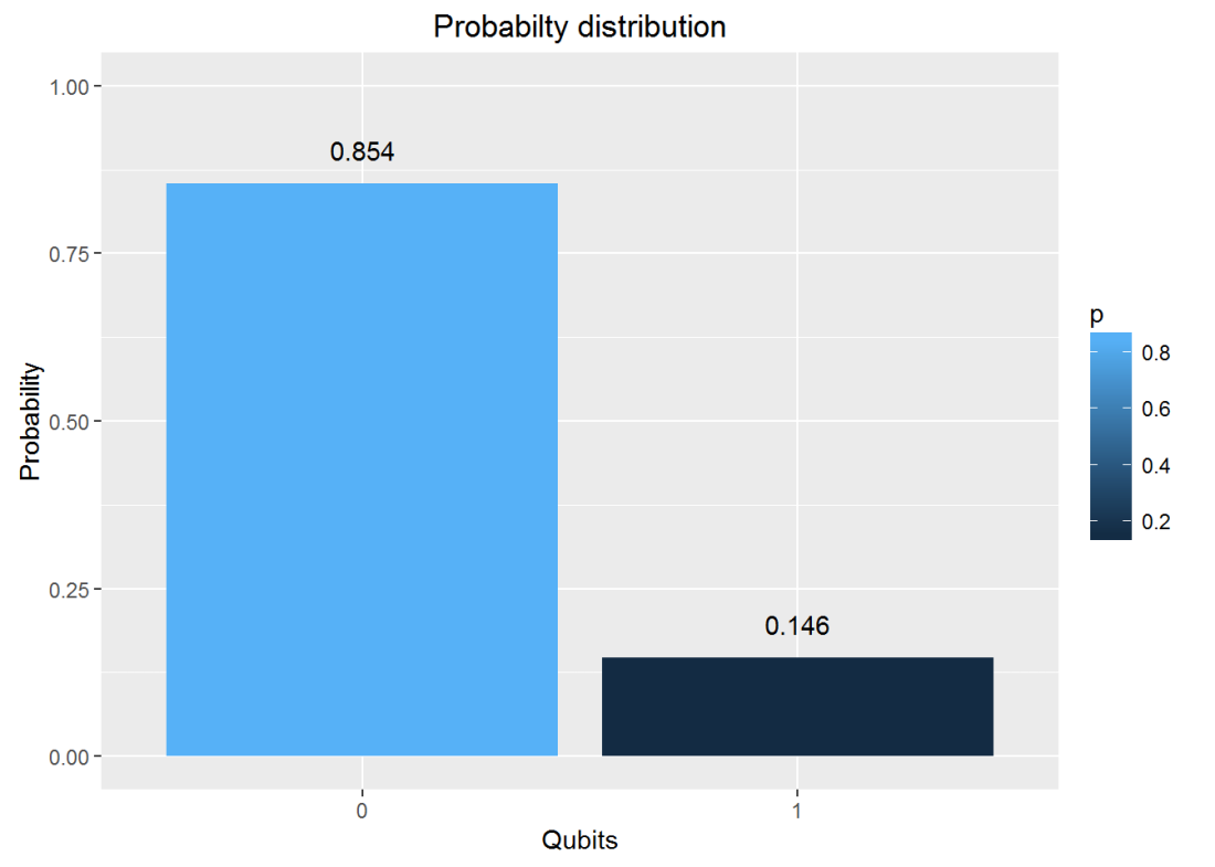
measurement(a)
##           0         1
## v 0.8535534 0.1464466

5. Plot the measurements

plotMeasurement(q1)

unnamed-chunk-5-1

plotMeasurement(Hadamard(q0))

unnamed-chunk-5-2

a = measurement(SGate(TGate(Hadamard(TGate(Hadamard(q0))))))
plotMeasurement(a)

unnamed-chunk-5-3

6. Using the QCSimulator for one of the Bell tests
Here I compute the following measurement of  Bell state ZW  with the QCSimulator
Untitled

When this is simulated on IBM’s Quantum Experience the result is
Untitled

Below I simulate the same on my R based QCSimulator

# Compute the effect of the Composite H gate with the Identity matrix (I)
a=kronecker(H,I,"*")
a
##           [,1]      [,2]       [,3]       [,4]
## [1,] 0.7071068 0.0000000  0.7071068  0.0000000
## [2,] 0.0000000 0.7071068  0.0000000  0.7071068
## [3,] 0.7071068 0.0000000 -0.7071068  0.0000000
## [4,] 0.0000000 0.7071068  0.0000000 -0.7071068
# Compute the applcation of CNOT on this result
b = CNOT(a)
b
##           [,1]      [,2]       [,3]       [,4]
## [1,] 0.7071068 0.0000000  0.7071068  0.0000000
## [2,] 0.0000000 0.7071068  0.0000000  0.7071068
## [3,] 0.0000000 0.7071068  0.0000000 -0.7071068
## [4,] 0.7071068 0.0000000 -0.7071068  0.0000000
# Obtain the result of CNOT on q00
c = b %*% q00
c
##           [,1]
## [1,] 0.7071068
## [2,] 0.0000000
## [3,] 0.0000000
## [4,] 0.7071068
# Compute the effect of the composite HxTxHxS gates and the Identity matrix(I) for measurement
d=Hadamard(TGate(Hadamard(SGate(I))))
e=kronecker(I, d,"*")

# Applying  the composite gate on the output 'c'
f = e %*% c
# Measure the output
g <- measurement(f)
g
##          00        01        10        11
## v 0.4267767 0.0732233 0.0732233 0.4267767
#Plot the measurement
plotMeasurement(g)

aaunnamed-chunk-6-1
which is exactly the result obtained with IBM’s Quantum Experience!

Conclusion : In  this post I dwell on 1 and 2-qubit quantum gates and explore their operation. I have started to construct a  R based Quantum Computing Simulator. I hope to have a reasonable simulator in the next couple of months. Let’s see.

Watch this space!

Disclaimer: This article represents the author’s viewpoint only and doesn’t necessarily represent IBM’s positions, strategies or opinions

References
1.  IBM Quantum Experience – User Guide
2. Quantum Mechanics and Quantum Conputing, UC Berkeley

Also see
1.  Venturing into IBM’s Quantum Experience
2. Going deeper into IBM’s Quantum Experience!
3.  A primer on Qubits, Quantum gates and Quantum Operations

You may also like
1.  My TEDx talk on the “Internet of Things”
2. Experiments with deblurring using OpenCV
3. TWS-5: Google’s Page Rank: Predicting the movements of a random web walker

For more posts see
Index of posts

A primer on Qubits, Quantum gates and Quantum Operations

Introduction: After my initial encounter with IBM’s Quantum Experience, and my playing around with qubits, quantum gates and trying out the Bell experiment I can now say that I am fairly hooked to quantum computing.

So, I decided that  before going any  further,  that I  needed to  spend a little time more, getting to know more about the basics of Dirac’s bra-ket notation, qubits and ensuring that my knowledge is properly “chunked” ( See Learning to Learn: Powerful mental tools to master tough subjects, a really good course!!)

So, I started to look around for material on Quantum Computing, and finally landed on the classic course “Quantum Mechanics and Quantum Computing”, from University of California, Berkeley by Prof Umesh V Vazirani at edX. I have started to audit the course (listen in, without doing the assignments). The Prof is unbelievably good, and makes the topic both interesting and absorbing. This post is based on my notes of week 1 & 2 lectures. I have tried to articulate as best as I can, what I have understood of the lectures, though I would strongly recommend  you to, at least audit the archived course. By the way, I also had to refresh my knowledge of basic trigonometry and linear algebra. My knowledge of the basics of matrix manipulation, vectors etc. were buried deep within the sands of time. Luckily for me, they were reasonably intact.

A) Quantum states
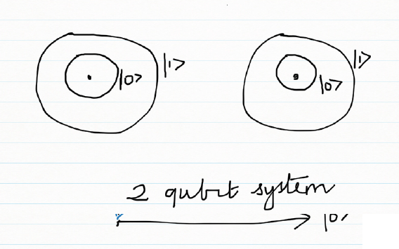
A hydrogen atom has 1 electron in orbit. The electron can be either in the idle state or in the excited state. We can represent the idle state with |0> and the excited state with |1>, which is Dirac’s ‘ket’ notation.

Untitled

This electron will be in a superposition state which is represented by
Ψ = α |0> + β |1> where α & β are complex numbers and obey | α|2 + | β|2 = 1
For e.g. we could have the superposition state
\varphi= \frac{1}{2} + \frac{1i}{2}|0> + \frac{1}{\sqrt{2}}|1>
It can be seen that | α|2 = \frac{1}{2} and | β|2 = = \frac{1}{2}
For a complex number α = a+ bi  == > | α| = \sqrt{a^{2} + b^{2}}

B) Measurement
However, when the electron or the qubit is measured,  the state of superposition collapses to either |0> or |1> with the following probability’s

The resulting state is
|0> with probability | α|2
|1> with probability | β |2

And | α|2 + | β|2 = 1 because the sum of the probabilities must add up to 1  i.e. \sum p_{i} = 1

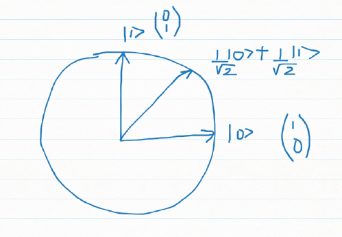
C) Geometric interpretation
Let us consider a qubit that is in a superposition state
Ψ = α |0> + β |1> where α & β are complex numbers and obey | α|2 + | β|2 = 1

We can write this as a vector  \begin{pmatrix} \alpha\\ \beta \end{pmatrix} representing the state of the electron

It can be seen that if
\alpha=1 and \beta=0 then |0> = \begin{pmatrix}1\\ 0\end{pmatrix}
and
\alpha=0 and \beta=1  then |1> = \begin{pmatrix}0\\ 1\end{pmatrix}
Untitled

Measuring a qubit in standard basis
If we represent the qubit geometrically then the superposition can be represented as a vector which makes an angle theta with |0>
\varphi = cos\theta|0> + sin\theta|1>

Measuring this  \varphi is the projection of on one of the standard basis |0> or |1>
The output is is |0> with probability cos^{2}\theta and
|1> with probability sin^{2}\theta

D) Measuring a qubit in any basis
Untitled
The qubit can be measured in any arbitrary basis. For e.g.  if
Ψ = α |0> + β |1>   and we have the diagonal basis
|u>| and |u’> as shown and Ψ makes an angle \theta with |u> then we can write

|u> with probability cos2Θ
And |u’> with probability sin2Θ

E) K Qubit system
Let us assume that we have a Quantum System with k qubits
|0>, |1>, |2>… |k-1>

The qubit will be in a superimposed state
Ψ = α0 |0>+ α1 |1> + α2|2> + … + αk-1 |k-1>
Where αj is a complex vector with the property ∑ αj = 1

Here Ψ is a unit vector in a K dimensional complex vector space, known as Hilbert Space
For e.g. a 3 qubit quantum system
\varphi = \frac{1}{2}+\frac{i}{2}|0> - \frac{1}{2} |1> + \frac{1}{2}|2>
Then P(0) = ½ P(1) = ¼ and P(2) = ¼   ∑Pj = 1

We could also write
\varphi = \begin{pmatrix} \alpha_{0}\\ \alpha_{1}\\ .. \\\alpha_{k-1}\\\end{pmatrix}
Or
Ψ = α0 |0>+ α1 |1> + α2|2> + … + αk-1 |k-1>

F) Measuring the angle between 2 complex vectors
To measure the angle between 2 complex vectors
\varphi = \begin{pmatrix} \alpha_{0}\\ \alpha_{1}\\\alpha_{2}\\\end{pmatrix}
And
\phi = \begin{pmatrix} \beta_{0}\\ \beta_{1}\\\beta_{2}\\\end{pmatrix}
we need to take the inner product of the complex conjugate of the 1st vector and the 2nd
cosΘ = inner product  => \bar{\varphi} . \phi
cos\theta = \bar\alpha_{0}\beta_{0} + \bar\alpha_{1}\beta_{1} + \bar\alpha_{2}\beta_{2}

For e.g.
If \varphi = \frac{1}{2} |0> + \frac{\sqrt 3}{2}|1> which makes 60 degrees with the |0> basis
And
\phi = \frac{1}{\sqrt 2} |0> + \frac{1}{\sqrt 2}|1> which is the diagonal |+> basis
Then the angle between these 2 vectors are obtained by taking the inner product
cosΘ =  ½ * 1/√2 + √3/2 * ½

G) Measuring Ψ in |+> or |-> basis
For e.g. if
\varphi = \frac{1}{2} |0> + \frac{\sqrt 3}{2}|1>   – (A)

Then we can specify/measure Ψ in |+> or |-> basis as follow
|+> = 1/√2(|0> + |1>) and |-> = 1/√2(|0> – |1>)
Or |0> = 1/√2(|+> + |->)   and |1> = 1/√2(|+> – |->)

We can write
Ψ= α|+> + β|->

Substituting for |0> and |1>  in (A) we get
\varphi = \frac{1+ \sqrt 3}{2 \sqrt 2} |+> \frac{1 - \sqrt 3 }{2 \sqrt 2} |->

H) Quantum gates
I) Clifford gates
Pauli gates
a) Pauli X
The Pauli X gate does a bit flip
|0> ==>  X|0> ==> |1>
|1> ==>  X|1> ==> |0>
and is represented
\begin{pmatrix}0&1\\1&0\end{pmatrix}

b) Pauli Z
This gates does a phase flip and is represented as the 2 x 2 unitary matrix
\begin{pmatrix}1&0\\0&-1\end{pmatrix}

c) Pauli Y
The Pauli operator Y  does both  a bit and a phase flip. The Y operator is represented as
\begin{pmatrix}0&-i\\i&0\end{pmatrix}

K) Superposition gates
Superposition is the concept that adding quantum states together results in a new quantum state. There are 3 gates that perform superposition of qubits the H, S and S’ gate.
a) H gate (Hadamard gate)
The H gate, also known as the Hadamard Gate when applied |0> state results in the qubit being half the time in  |0> and the other half in |1>
The H gate can be represented as
1/√2 \begin{pmatrix}1 & 1\\ 1 & -1\end{pmatrix}

b) S gate
The S gate can be represented as
\begin{pmatrix}1 & 0\\ 0 & i\end{pmatrix}

c) S’ gate
And the S’ gate is
\begin{pmatrix}1 & 0\\ 0 & -i\end{pmatrix}

L) Non-Clifford Gates
The quantum gates discussed in my earlier post Pauli X, Y, Z, H, S and S1 are members of a special group of gates known as the ‘Clifford group’.
The non-Clifford gates, discussed are the T and  Tǂ gates

These are given by
T = \begin{pmatrix}1 & 0\\ 0 & e^{^{i\prod /4}}\end{pmatrix}
Tǂ =\begin{pmatrix}1 & 0\\ 0 & e^{^{-i\prod /4}}\end{pmatrix}

M) 2 qubit system
A 2 qubit system
Untitled

A 2 qubit system is a superposition of all possible 2 qubit states. A 2 qubit system and can be represented as

Ψ = α00 |00> + α01 |01> + α10 |10> + α11 |11>

Measuring the 2 qubit system, as earlier, results in the collapse of the superposition and the result is one of 4 qubit states. The probability of the measure state is the square of the amplitude | αij|2

N) Entanglement
A  2 qubit system in which we have
Ψ = α0 |0> + α1 |1> and Φ= β0 |0> + β1 |1> the superimposed state is obtained by taking the tensor product of the 2 qubits
\chi = (\alpha_{0} |0> + \alpha_{1}|1>)\otimes  (\beta_{0} |0> + \beta_{1} |1>)
Where  \otimes is the tensor product

The state
Ψ = 1/√2|00> + 1/√2|11>
Is called an ‘entangled’ state because it cannot  be reduced to a product of 2 vectors

N) 2 qubit gates

Untitled

A 2 qubit system is a superposition of all possible 2 qubit states. A 2 qubit system and can be represented as
Ψ = α00 |00> + α01 |01> + α10 |10> + α11 |11>

Measuring the 2 qubit system, as earlier, results in the collapse of the superposition and the result is one of 4 qubit states. The probability of the measure state is the square of the amplitude | αij|2
More specifically a 2 qubit system in which we have
Ψ = α0 |0> + α1 |1> and Φ= β0 |0> + β1 |1> the superimposed state is obtained by taking the tensor product of the 2 qubits
\chi = (\alpha_{0} |0> + \alpha_{1}|1>)\otimes  (\beta_{0} |0> + \beta_{1} |1>)

Where \otimes is the tensor product
The state
Ψ = 1/√2|00> + 1/√2|11>
Is called an ‘entangled’ state because it cannot  be reduced to a product of 2 vectors
A quantum gate is a 2 x 2 unitary matrix U such that
α0 |0> + α1 |1>    == > Quantum Gate == > β0|0> + β1 |1>

Unitary functions: In mathematics, a complex square matrix U is unitary if its conjugate transpose U* is also its inverse
If
U=\begin{pmatrix}a & c \\b & d\end{pmatrix}
And U* = \begin{pmatrix}\bar a & \bar b \\ \bar c & \bar d\end{pmatrix}
Then
UU* = I where I is the Identity matrix

2 qubit gates is  4 x 4 unitary matrix
For a 2 qubit that is in the superposition state
Ψ = α00 |00> + α01 |01> + α10 |10> + α11 |11>

A 2 qubit gate’s operation on Ψ is
\begin{pmatrix}a & e & i & m \\ b & f & j & n\\ c & g & k & o\\ d & h & l & p\end{pmatrix} * \begin{pmatrix}\alpha_{00}\\ \alpha_{01}\\ \alpha_{10}\\\alpha_{11}\end{pmatrix}

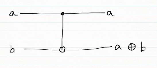
One important 2 qubit gate is the CNOT gate which is shown  below

Untitled


The CNOT gate is represented by the following unitary matrix
\begin{pmatrix}1 & 0 & 0 & 0\\ 0 & 1 & 0 & 0 \\0 & 0  & 0  & 1\\ 0 & 0 & 1 & 0\end{pmatrix}

If 2  2×2 qubit gates were applied to 2 qubits the composite gate would be Tensor product of the 2 matrices

u1 = \begin{pmatrix}a & c\\ b & d\end{pmatrix}
u2 = \begin{pmatrix}e & g\\ f & h\end{pmatrix}
then
U= u1 \otimes u2
U = \begin{pmatrix}a\begin{pmatrix}e & g\\ f & h\end{pmatrix} & c\begin{pmatrix}a & c\\ b & d\end{pmatrix}\\ b \begin{pmatrix}a & c \\ b & d\end{pmatrix}& d\begin{pmatrix}a & c\\ b & d\end{pmatrix}\end{pmatrix}
The above product is also known as the Kronecker product

O) Tensor product of 2 qubits
Ψ = α0 |0> + α1 |1> and Φ= β0 |0> + β1 |1>
$latex \varphi \otimes \phi= α0 β0|0>|0> + α0 β1|0>|1> + α1 β0|1>|0> + α1 β1|1>|1>
= α0 β0|00> + α0 β1|01> + α1 β0|10> + α1 β1|11>
Untitled

If a Z gate and a Hadamard gate H were applied on 2 qubits, it is interest to know what the resulting composite gate would be.

Z = \begin{pmatrix}1 & 0\\ 0 & -1\end{pmatrix} and H = \begin{pmatrix}\frac{1}{\sqrt 2} & \frac{1}{\sqrt 2} \\ \frac{1}{\sqrt 2} & \frac{-1}{\sqrt 2}\end{pmatrix}
The composite gate is obtained by the tensor product of
Z \otimes H
Hence the result of the composite gate is
=\begin{pmatrix}1\begin{pmatrix}\frac{1}{\sqrt 2}   & \frac{1}{\sqrt 2}\\  \frac{1}{\sqrt 2}& \frac{-1}{\sqrt 2}\end{pmatrix} & 0\\ 0 & -1\begin{pmatrix}\frac{1}{\sqrt 2} & \frac{1}{\sqrt 2}\\ \frac{1}{\sqrt 2} &\frac{-1}{\sqrt 2} \end{pmatrix}\end{pmatrix}
=\begin{pmatrix}\begin{pmatrix}\frac{1}{\sqrt 2}   & \frac{1}{\sqrt 2}\\  \frac{1}{\sqrt 2}& \frac{-1}{\sqrt 2}\end{pmatrix} & 0\\ 0 & -\begin{pmatrix}\frac{-1}{\sqrt 2} & \frac{-1}{\sqrt 2}\\ \frac{-1}{\sqrt 2} &\frac{1}{\sqrt 2} \end{pmatrix}\end{pmatrix}

which is the entangled state.

Conclusion: This post includes most of the required basics to get started on Quantum Computing. I will probably add another post detailing the operations of the Quantum Gates on qubits.

Note:
1.The equations and matrices have been created using LaTeX notation using the online LaTex equation creator
2. The figures have been created using the app Bamboo Paper, which I think is cooler than creating in Powerpoint

Also see
1.Venturing into IBM’s Quantum Experience
2. Going deeper into IBM’s Quantum Experience!

You may also like
1.  Sixer – R package cricketr’s new Shiny avatar
2. Natural language processing: What would Shakespeare say?
3. Sea shells on the seashore
4. How to program – Some essential tips
5. Rock N’ Roll with Bluemix, Cloudant & NodeExpress
6. The Many Faces of Latency

Going deeper into IBM’s Quantum Experience!

Introduction

In this post I delve deeper into IBM’s Quantum Experience. As mentioned in my earlier post “Venturing into IBM’s Quantum Experience”, IBM, has opened up its Quantum computing environment, to the general public, as the Quantum Experience. The access to Quantum Experience is through IBM’s Platform as a Service (PaaS) offering, Bluemix™. Clearly this is a great engineering feat, which integrates the highly precise environment of Quantum Computing, where the qubits are maintained at 5 milliKelvin, and the IBM Bluemix PaaS environment on Softlayer. The Quantum Experience, is in fact Quantum Computing as a Service (QCaaS).  In my opinion, the Quantum Experience, provides a glimpse of tomorrow, today,

Disclaimer: This article represents the author’s viewpoint only and doesn’t necessarily represent IBM’s positions, strategies or opinions

Note: Also by the way, feel free to holler if you find anything incorrect or off the mark in my post. I am just getting started on quantum computing so there may be slip ups.

A) Bloch sphere

6In my earlier post the operations of the X, Y, Z, H, S, and S1 were measured using the standard or diagonal basis and the results were in probabilities of the qubit(s). However, the probabilities alone, in the standard basis, are not enough to specify a quantum state because it does not capture the phase of the superposition. A convenient representation for a qubit is the Bloch sphere.

The general state of a quantum two-level system can be written in the form

|ψ⟩=α|0⟩+β|1⟩,

Where α and β are complex numbers with |α|2+|β|2=1. This leads to the “canonical” parameterized form

|ψ⟩= cos Θ/2 |0> + e sin Θ/2 |1>                        (A)

in terms of only two real numbers θ and φ, with natural ranges 0 ≤ θ ≤ π and 0 ≤ φ ≤ 2π. These are the same as the polar angles in 3-dimensional spherical coordinates, and this leads to the representation of the state (1) as a point on a unit sphere called the Bloch sphere.

In the notation of (A), the state |0> is represented by the North pole, and the state |1> by the South pole. Note:  The states |0> and |1> , n the Bloch sphere are not orthogonal to each other. The states on the equator of the Bloch sphere, correspond to superpositions of |0> and |1> with equal weights (θ = π∕2), and different phases, parameterized by the azimuthal angle φ (the “longitude”)

In the picture below  Bloch  measurements  are performed on the operations on the qubits

1

The results of the Bloch measurements for the combination of  quantum gates are shown below

i) Quantum gate operations and Bloch measurements

4

ii) Quantum gate operations as Superposition operations

5

B) Classical vs Quantum computing
A classical computer that has N-bits has 2^{N}possible configurations. However, at any
one point in time, it can be in one, and only one of  2N  configurations. Interestingly, the quantum computer also takes in a n -bit number and outputs a n -bit number; but because of the superposition principle and the possibility of entanglement, the intermediate state is very different.

A system which had N different mutually exclusive states can be represented as |1>, |2>. . . |N> using the Dirac’s bra-ket notation

A pure quantum state is a superposition of all these states
Φ = α1 1> + α2 2> + …. + αN N>
To describe it requires complex numbers, giving a lot more room for maneuvering.

C) The CNOT gate
The CNOT gate or the Controlled-Not gate is an example of a two-qubit quantum gate. The CNOT gate’s action is to flip (apply a NOT or X gate to) the target qubit if the control qubit is 1; otherwise it does nothing. The CNOT plays the role of the classical XOR gate, but unlike the XOR, The CNOT gate is a two-output gate and is reversible It is represented by the matrix by the following 4 x 4 matrix

\begin{pmatrix}1 & 0 & 0 &0 \\ 0 & 1 & 0 &0 \\  0& 0 &  0&1 \\ 0 & 0 & 1 & 0\end{pmatrix}

The CNOT gate flips the target bit if the control bit is 1, otherwise it does nothing if it’s 0:

More specifically
CNOT|0>|b> = |0>|b>
CNOT|1>|b>= |1>|1 – b>

The operation of the CNOT gate can be elaborated as below
The 2-qubit basis states can be represented as four-dimensional vectors
|00> = \begin{pmatrix} 1& 0 & 0 & 0 \end{pmatrix}^{T}
|01> = \begin{pmatrix} 0& 1 & 0 & 0 \end{pmatrix}^{T}
|10> = \begin{pmatrix} 0& 0 & 1 & 0 \end{pmatrix}^{T}
|11> = \begin{pmatrix} 0& 0 & 0 & 1 \end{pmatrix}^{T}

For example, a quantum state may be expanded as a linear combination of this basis:
|ψ⟩=a|00⟩+b|01⟩+c|10⟩+d|11⟩

The CNOT matrix can  be applied as below
CNOT*|ψ⟩=CNOT*(a|00⟩+b|01⟩+c|10⟩+d|11⟩)
= a*CNOT*|00⟩+…+d*CNOT*|11⟩

where you perform standard matrix multiplication on the basis vectors to get:
CNOT*|ψ⟩=a|00⟩+b|01⟩+c|11⟩+d|10⟩

In other words, the CNOT gate has transformed
|10⟩↦|11⟩ and |11⟩↦|10⟩

i) CNOT operations in R code

# CNOT gate
cnot= matrix(c(1,0,0,0,0,1,0,0,0,0,0,1,0,0,1,0),nrow=4,ncol=4)
cnot
##      [,1] [,2] [,3] [,4]
## [1,]    1    0    0    0
## [2,]    0    1    0    0
## [3,]    0    0    0    1
## [4,]    0    0    1    0
#a. Qubit |00> 
q00=matrix(c(1,0,0,0),nrow=4,ncol=1)
q00
##      [,1]
## [1,]    1
## [2,]    0
## [3,]    0
## [4,]    0
# CNOT *q00 ==> q00
a <- cnot %*% q00
a
##      [,1]
## [1,]    1
## [2,]    0
## [3,]    0
## [4,]    0
#b.Qubit |01>
q01=matrix(c(0,1,0,0),nrow=4,ncol=1)
q01
##      [,1]
## [1,]    0
## [2,]    1
## [3,]    0
## [4,]    0
# CNOT *q01 ==> q01
a <- cnot %*% q01
a
##      [,1]
## [1,]    0
## [2,]    1
## [3,]    0
## [4,]    0
#c. Qubit |10>
q10=matrix(c(0,0,1,0),nrow=4,ncol=1)
q10
##      [,1]
## [1,]    0
## [2,]    0
## [3,]    1
## [4,]    0
# CNOT *q10 ==> q11
a <- cnot %*% q10
a
##      [,1]
## [1,]    0
## [2,]    0
## [3,]    0
## [4,]    1
#d. Qubit |11>
q11=matrix(c(0,0,0,1),nrow=4,ncol=1)
q11
##      [,1]
## [1,]    0
## [2,]    0
## [3,]    0
## [4,]    1
# CNOT *q11 ==> q10
a <- cnot %*% q11
a
##      [,1]
## [1,]    0
## [2,]    0
## [3,]    1
## [4,]    0

D) Non Clifford gates
The quantum gates discussed in my earlier post (Pauli X, Y, Z, H, S and S1) and the CNOT are members of a special group of gates known as the ‘Clifford group’. These gates can be simulated efficiently on a classical computer. Therefore, the Clifford group is not universal.  A finite set of gates that can approximate any arbitrary unitary matrix is known as a universal gate set. This is similar,  to how certain sets of classical logic gates, such as {AND, NOT}, are functionally complete and can be used to build any Boolean function ( I remember this axiom/fact from my Digital Electronics -101 class about 3  decades back!).

Adding almost any non-Clifford gate to single-qubit Clifford gates and CNOT gates makes the group universal which I presume can simulate any arbitrary unitary matrix.  The non-Clifford gates, discussed are the T and  Tǂ gates

These are given by

T = \begin{pmatrix}1 & 0\\ 0 & e^{^{i\prod /4}}\end{pmatrix}

Tǂ =\begin{pmatrix}1 & 0\\ 0 & e^{^{-i\prod /4}}\end{pmatrix}

i) T gate operations
The T gate makes it possible to reach  different points of the Bloch sphere.  By increasing the number of T-gates in the quantum circuit ( we start to cover the Bloch sphere more densely with states that can be reached

ii)  T Gates of depth 2 – Computational Measurement
9

Simulating in Composer
10

iii) Simulating in R Code
Measurement only gives the real part and does not provide info on phase

# T Gate 
T=matrix(c(1,0,0,exp(1i*pi/4)),nrow=2,ncol=2)
# Simulating T Gate depth-2 - Computational  measurement
a=S%*%T%*%H%*%T%*%H%*%q0
a
##                      [,1]
## [1,] 0.8535534+0.3535534i
## [2,] 0.1464466+0.3535534i

iv) 2 T Gates – Bloch  Measurement
7

Bloch measurement

8

v) Simulating T gate in R code
This gives the phase values as shown in the Bloch sphere

# Simulating T Gate depth-2 - Bloch measurement (use a diagonal basis H gate in front)
a=H%*%S%*%T%*%H%*%T%*%H%*%q0
a
##                [,1]
## [1,] 0.7071068+0.5i
## [2,] 0.5000000+0.0i


E) Quantum Entanglement – The case of ‘The Spooky action at a distance’
One of the infamous counter-intuitive ideas of quantum mechanics is that two systems that appear too far apart to influence each other can nevertheless behave in ways that, though individually random, are too strongly correlated to be described by any classical local theory.  For e.g. when the 1st qubit of a pair of “quantum  entangled” qubits are measured, this automatically determines the 2nd qubit, though the individual qubits may be separated by extremely large distances. It appears that the measurement of the first qubit cannot affect the 2nd qubit which is too far apart to be be influenced and also given the fact  that nothing can travel faster than the speed of light.  More specifically

“Suppose Alice has the first qubit of the pair, and Bob has the second. If Alice measures her qubit in the computational basis and gets outcome b ∈ {0, 1},  then the state collapses to |bb> . In other words the measurements and outcome of the 1st qubit determines the outcome of the  2nd qubit . How weird is that?

Similarly, if Alice measures her qubit in some other basis, this will collapse the joint state (including Bob’s qubit) to some state that depends on her measurement basis as well as its outcome. Somehow Alice’s action seems to have an instantaneous effect on Bob’s side—even if the two qubits are light-years apart!”

How weird is that!

Einstein, whose theory of relativity posits that information and causation cannot travel faster than the speed of light, was greatly troubled by this, . Einstein called such effects of entanglement “spooky action at a distance”.

In the 1960s, John Bell devised entanglement-based experiments whose behavior cannot be reproduced by any “local realist” theory where the implication of local and realist is given below

Locality: No information can travel faster than the speed of light. There is a hidden variable that defines all the correlations.

Realism:  All observables have a definite value independent of the measurement

i) Bell state measurements
The mathematical proof for the Bell tests  are quite abstract  and mostly escaped my grasp. I  hope to get my arms around this beast, in the weeks and months to come. However, I understood how to run the tests and perform the calculations which are included below.  I have executed the Bell Tests on

a) Ideal Quantum Processor (Simulator with ideal conditions)
b) Realistic Quantum Processor (Simulator with realistic conditions)
c) Real Quantum Processor. For this I used 8192 ‘shots’ repeats of the experiment

I finally calculate |C| for all 3 tests

The steps involved in calculating |C|
1.  Execute ZW, ZV, XW, XV
2. Calculate = P(00) + P(11) – P(01) – P(10)
3.  Finally |C| = ZW + ZV + XW – XV

Preparation of Qubit |00>
The qubits are in state |00> The H gate  takes the first qubit to the equal superposition

1/√2(|00> + |10>)  and the CNOT gate flips the second qubit if the first is excited, making the state  1/√2(|00> + |11>). This is the entangled state (commonly called a Bell state)

11

Simulating in Composer
This prepares the entangled state 1/√2(|00> + |11>)

12

It can be seen that the the qubits |00> and  |11> are created

1) Simulations on Ideal Quantum processor

a) Bell state ZW (Ideal) 
13
Simulation
24
P(00) = 0.427
P(01) = 0.073
P(10) =0.073
P(11) = 0.427

b) Bell state ZV (Ideal) 
14

Simulation

25
P(00) = 0.427
P(01) = 0.073
P(10) =0.073
P(11) = 0.427

c) Bell state XW (Ideal)
26

Measurement
27
P(00) = 0.427
P(01) = 0.073
P(10) =0.073
P(11) = 0.427

d) Bell state XV (Ideal)
28

Simulating Bell State XV in Composer
16
P(00) = 0.073
P(01) = 0.473
P(10) = 0.473
P(11) =0.73

Bell test measurement in Ideal Quantum Processor are given below
Untitled

For the Ideal Quantum Processor
|C) = 2.832

2) Simulations on the Realistic  Quantum Processor
The Bell tests above were simulated on Realistic Quantum Processor. The results are included below

Untitled

For the Realistic Quantum Processor
|C) = 2.523

3) Real IBM Quantum  Processor (8192 shots)
Finally the Bell Tests were executed in IBM’s Real Quantum Processor for 8192 shots, each requiring 5 standard units. The tests were queued, executed and the results sent by mail. The results are included below
a) Bell State ZW measurement (Real)
29

b) Bell state ZV measurement  (Real)
30
c) Bell State XW measurement (Real)
31
d) Bell state XV measurement (Real)

32

;

The results were tabulated and |C| computed. Bell test measurement in Real Quantum Processor are given below

Untitled

The Bell measurements on the Reak Quantum Processor is
|C) = 2.509

Conclusion
This post included details on the CNOT and the non-Clifford gates. The Bell tests were performed on all 3 processors Ideal, Realistic and Real Quantum Processors and in each case the |C| > 2. While I have been to execute the tests I will definitely have to spend more time understanding the nuances.

I hope to continue this journey into quantum computing the months to come. Watch this space!

Disclaimer: This article represents the author’s viewpoint only and doesn’t necessarily represent IBM’s positions, strategies or opinions

References
1.IBM Quantum Experience – User Guide
2.Quantum Computing lecture notes – Ronald De Wolf
3.Bloch sphere
4.Basic concepts in quantum computation
5.Physics Stack Exchange

You may also like
1.Revisiting crimes against women in India
2.Natural language processing: What would Shakespeare say?
3. My book ‘Practical Machine Learning with R and Python’ on Amazon
4. Introducing QCSimulator: A 5-qubit quantum computing simulator in R
5.Beaten by sheer pace – Cricket analytics with yorkr
6.A method for optimal bandwidth usage by auctioning available bandwidth using the OpenFlow protocol
7.TWS-4: Gossip protocol: Epidemics and rumors to the rescue
8.Bend it like Bluemix, MongoDB using Auto-scale – Part 1!
9.Fun simulation of a Chain in Android
10.Cricket analytics with cricketr in paperback and Kindle versions

The brave, new frontiers of computing

This article was published in Telecom Asia, 21 March 2014 – The brave new frontiers of computing

Von Neumann reference architecture and the sequential processing of Turing machines have been the basis for ‘classical’ computers for the last 6 decades. The juggernaut of technology has resulted in faster and denser processors being churned out inexorably by the semiconductor industry, substantiating Gordon Moore’s claim of transistors density in chips doubling every 18 months, now famously known as Moore’s law. These days we have processors with an excess of billion transistors. We are now reaching the physical limit of the number of transistors on a chip. There is now an imminent need to look at alternative paradigms to crack problems of the internet age, confronting human which cannot be solved by classical computing

In the last decade or so 3 new, radical and lateral paradigms have surfaced which hold tremendous promise. They are

i) Deep learning ii) Quantum computing and iii) Genetic programming.

These techniques hold enormous potential and may offer solutions to problems which would take classical computers anywhere between a few years to a few decades to solve.

pregelDeep Learning:Deep Learning is a new area of Machine Learning research. The objective of deep learning is to bring Machine Learning closer to one of its original goals namely Artificial Intelligence. Deep Learning is based on multi-level neural networks called deep neural networks. Deep Learning works on large sets of unclassified data and is able to learn lower level patterns on which it builds higher level representations much the same way the human brain works.

Deep learning tries to mimic the human brain For example, the visual cortex shows a sequence of areas where signals flow from one level to the next. In the visual cortex the feature hierarchy represents input at a different level of abstraction, with more abstract features further up in the hierarchy, defined in terms of the lower-level ones. Deep Learning is based on the premise that humans organize ideas hierarchically and compose more abstract concepts from simpler ones.

Deep Learning algorithms generally requires powerful processors and works on enormous amounts of data to learn key features. The characteristic of Deep Learning algorithms is that the input is passed through several non-linearities before generating its output.

.

About 3 years ago, researcher’s at Google’s Brain ran a deep learning algorithm on 10 million still images extracted from Youtube, on 1000’s of extremely powerful processors called GPUs. Google’s Brain was able independently infer that these images consisted of a preponderance of cat’s videos. A seemingly trivial result, but of great significance as the algorithm inferred this result without any other input!

An interesting article in Nature, “The learning machines”, discusses how deep learning has proved useful for several scientific tasks including handwriting recognition, speech recognition, natural language processing, and in analyzing 3 dimensional images of brain slices etc.

The importance of Deep Learning has not been lost on the Tech titans like Google, Facebook, Microsoft and IBM which have all taken steps to stay ahead in this race.

Deep Learning is in its infancy and is still esoteric knowledge. Deep Learning is truly a fascinating area of research and may be the harbinger of the real breakthrough in Artificial Intelligence has been looking for in decades.

2Genetic Programming (GP) is another radical approach to computing. It had its origins in the early 1950’s and has been gaining traction in the last decade. Genetic programming (GP) is a branch of AI, based on Darwinian evolutionary principle of ‘natural selection’ and ‘survival of the fittest’. Essentially GP is a set of instructions and a fitness function to measure how well a computer program has performed a task. It is a specialization of genetic algorithms (GA) where each individual is a computer program.

Genetic Programming is a machine learning technique in which a population of computer programs are optimized according to ‘fitness criteria’ determined by a program’s ability to perform a given computational task. Fit programs survive and are moved along the evolutionary process. Fitness usually denotes the optimum value for a given objective function. In other words the fitness represents the ‘quality’ of a given solution over others. Individuals in a new population are created by the method of ‘reproduction’ and ‘cross over’.

In other words, the ‘most fit’ programs are crossbred and also possibly randomly mutated, creating a new generation of child programs. The unfit programs are discarded out and the best are bred again.

Once set up, the genetic program runs and evolves by itself and needs no further human input. Genetic Programming was pioneered by Stanford’s John Koza who was able to invent an antenna for NASA, identify proteins and invent electrical controllers.

The eerie part of GP is that the code is inscrutable. The program evolves and mutates into variations that cannot be easily reproduced. Clearly this is fodder for science fiction-like scenarios of self-aware, paranoid & psychopathic programs. Here is an interesting article that discusses this- This is What Happens When You Teach Machines the Power of Natural Selection

Quantum computing

3Computers of today from hardy mainframes to smartphones operate on binary logic. The entire edifice of today’s computing is based on the binary states of the semiconductor which can be either in the state of ‘0’ or ‘1’. All computation can be reduced to arithmetic and logical operation on binary digits or more simply, binary arithmetic. Quantum computers deviate significantly from the binary arithmetic of classical computers. The unit in the quantum computer is the ‘qubit’ which can be in state ‘0’, ‘1’ and both the state ‘0’ and ‘1’ through the principle of superposition.

To understand the power of quantum computing here is an excerpt from ArsTechnica “A tale of two qubits: How quantum computers work

Bits, either classical or quantum, are the simplest possible units of information…. Measuring a bit, either classical or quantum, will result in one of two possible outcomes. At first glance, this makes it sound like there is no difference between bits and qubits. In fact, the difference is not in the possible answers, but in the possible questions. For normal bits, only a single measurement is permitted, meaning that only a single question can be asked: Is this bit a zero or a one? In contrast, a qubit is a system which can be asked many, many different questions, but to each question, only one of two answers can be given”

The article further goes on to state that “Classical computer memories are constrained to exist at any given time as a simple list of zeros and ones. In contrast, in a single quantum memory many such combinations can all exist simultaneously. During a quantum algorithm, this symphony of possibilities is split and merged, eventually coalescing around a single solution. “

Having more than 1 qubit results in additional property called ‘quantum entanglement’. A pair of qubits cannot be described by the states of the individual qubits alone. Those states which exhibit extra correlations are described as ‘entangled’ states. Hence in the case of 2 qubits ‘the whole is greater than the sum of its parts”. Entanglement and superposition are the cornerstones which gives quantum computing its power. Here is a short and interesting animation of quantum computing

With classical computing techniques searching an unsorted phonebook of 10,000 entries, would require us to look up at least 5000 entries, while a quantum search algorithm only needs to guess 100 times. In other words it would take a quantum computer only 5000 guesses to search through a phonebook with 25 million names. That is the power of quantum computers!

Applications of quantum computers range from weather modeling, cryptography, solving problems that have been considered ‘intractable’ with classical computing methods. NASA is planning to use quantum computers in its search for exoplanets.

Deep Learning, Genetic Programming and Quantum Computing represent paradigmatic, lateral shifts in computing. They herald a new era in computing and will enable us to crack extremely complex problems in this Age of the Internet.

Classical computing will continue to play a role in a daily lives but for real world problems of the next decade & beyond it will be these 3 computing approaches that will hold the key to our future!

Find me on Google+